M-3 stabilizer circuits and isolated sector
RESTRICTED
J. Explanation
Stabilizer
Wiring
Diagram
M-3
Fig. 7
The M-3 has a two wire electrical system, a
power wire and a return wire.
The current for the operation of the stabi-
lizer comes through the number two pole of the
cannon plug from the source of power. The power
goes from number two pole to the stabilizer, tor-
que motor, bombsight and PDI switches.
The number one plug is the return connection.
(1) Stabi-
lizer
Circuit
When the stabilizer switch is closed, the
current flows through the brush contacting the
second slip ring from the bottom, or slip ring
2 (see diagram), from the slip ring to the gyro,
across a flexible lead, back to the lower slip
ring, and then to number one pole, thereby com-
pleting the circuit.
(2) Torque
Motor
Circuit
Close the torque (servo) switch. The current
flows to the torque motor, through the motor to
the return connection. The current going to the
motor branches to the clapper magnets. From the
clapper magnets the current goes to the two upper
slip rings, 4 and 3, (see Fig. 7). The current
from the left clapper magnet (magnet under the
brass gear) flows to the third slip ring, then to
the lower segments of the isolated sector, through
the contact made by the stabilizer brush, across
a flexible lead to the lower slip ring, and then
to number one pole, or the return.
When the right clapper magnet is energized,
the current flows through the fourth slip ring to
the upper segments of the isolated sector, through
the contact made by the stabilizer brush, across
a flexible lead to the lower slip ring, and then
to number one pole of the stabilizer cannon plug.
(3) Isolated
Sector
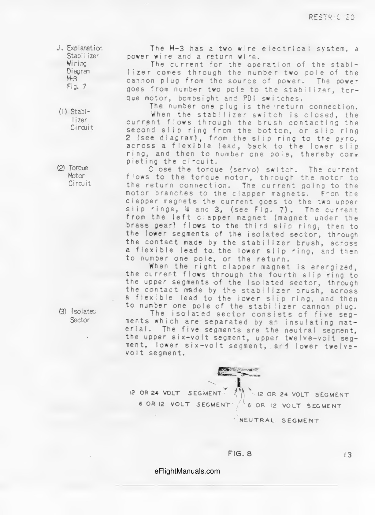
The isolated sector consists of five seg-
ments which are separated by an insulating mat-
erial. The five segments are the neutral segment,
the upper six-volt segment, upper twelve-volt seg-
ment, lower six-volt segment, and lower twelve-
volt segment.
FIG. 8
13