Stabilizer subsystem
The directional gyro, torque motor, clutches and indication linkage carried by the stabilizer housing.
Follow the mechanism
The directional gyro supplies the reference. The brush/sector and torque drive correct the cardan’s relationship to its surroundings.
Separate clutches couple this reference to the sight and autopilot/P.D.I. linkages.
Geometry follows the cited drawings and photographs. Unmeasured dimensions remain approximate; exploded spacing reveals existing model groups rather than a prescribed disassembly procedure.
Reference views
Inspect the full sheets as well as detail views. Figure numbers belong to their named document; similar-looking parts may be different variants.
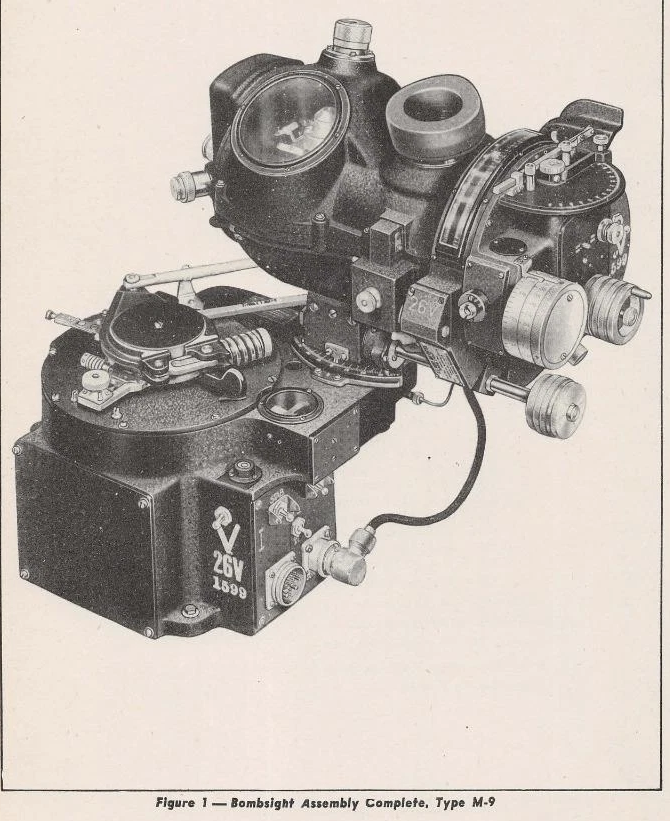
Bombsight Assembly Complete, Type M-9. Classify assembled/exploded/section state before registering a camera.
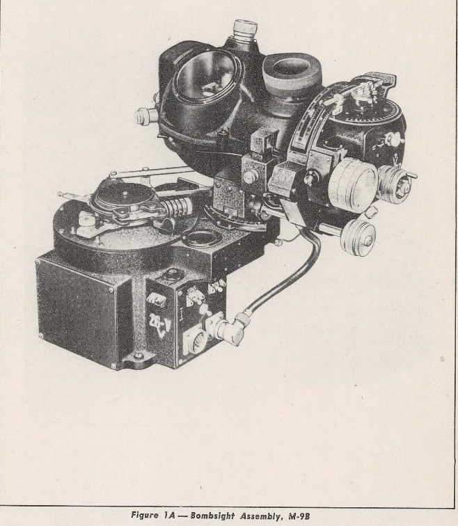
Bombsight Assembly, M-9B. Classify assembled/exploded/section state before registering a camera.
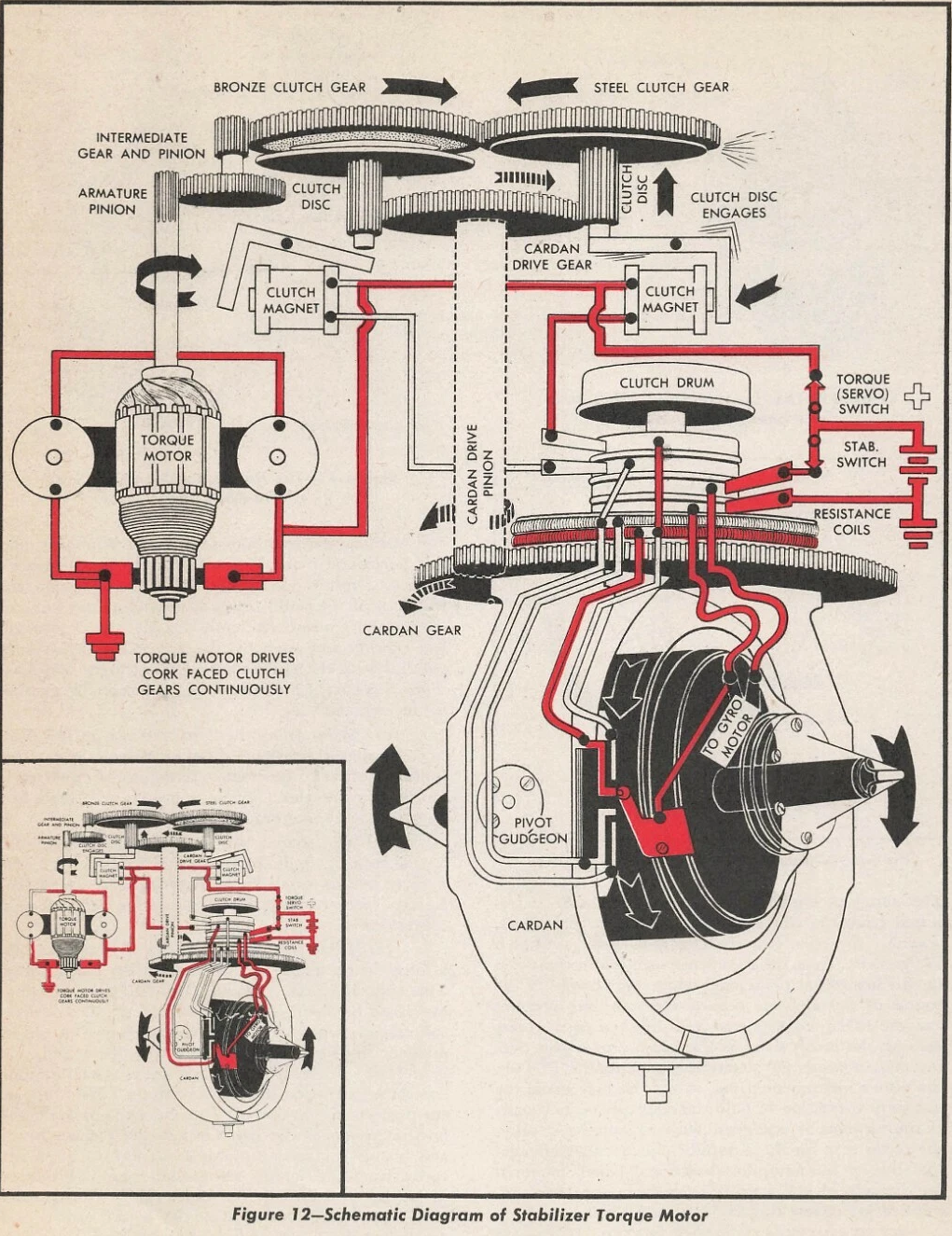
Schematic Diagram of Stabilizer Torque Motor. Classify assembled/exploded/section state before registering a camera.
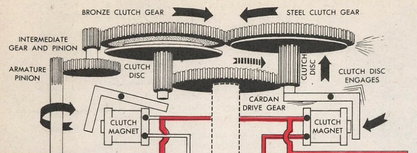
Opposed clutch gears and magnetic engagement
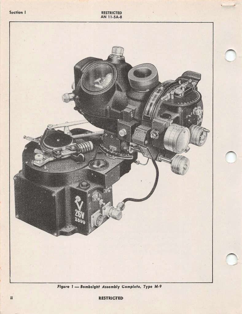
Untouched source sheet. Verify printed figure/item identity and neighboring context.
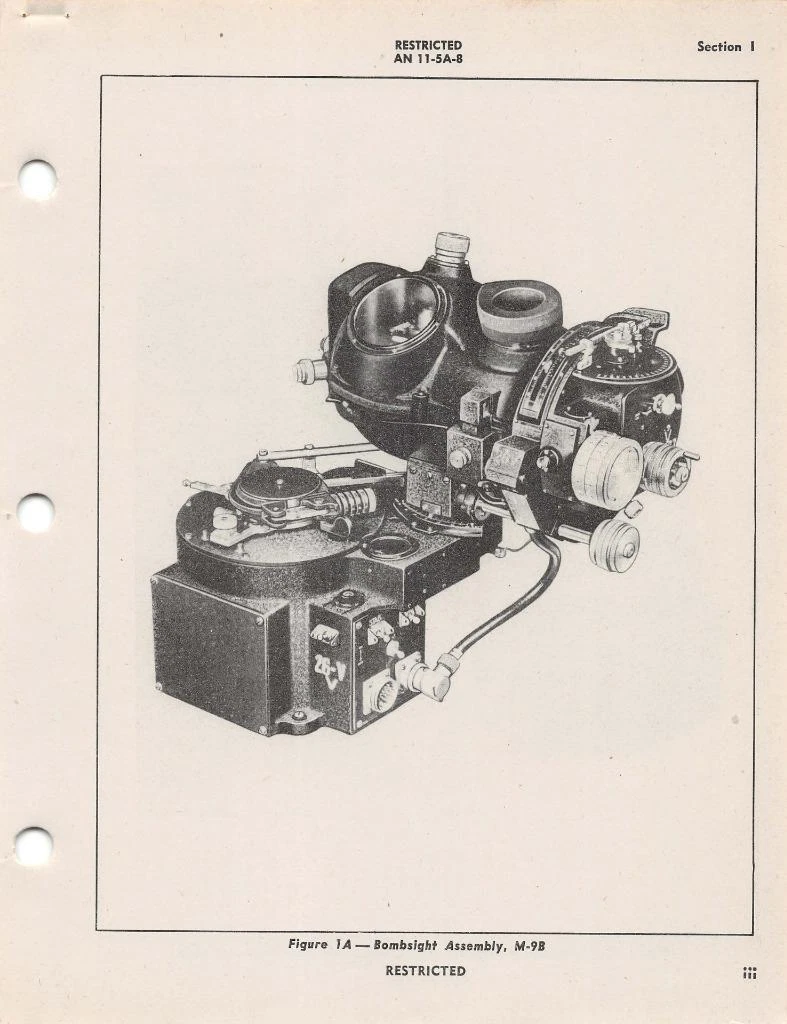
Untouched source sheet. Verify printed figure/item identity and neighboring context.