Precession and counter-balance bails
The case-mounted precession and counter-balance bails, together with the actuator that passes through the lower cardan gudgeon.
Follow the mechanism
The actuator stays with the cardan while the bails follow the tilting gyro case.
Their contact and balance roles are distinct from the fore-and-aft and lateral leveling controls of the sight-head gyro.
Shown in their relative installed positions with the surrounding case omitted. Contact clearances and force calibration remain unresolved.
Geometry follows the cited drawings and photographs. Unmeasured dimensions remain approximate; exploded spacing reveals existing model groups rather than a prescribed disassembly procedure.
Reference views
Inspect the full sheets as well as detail views. Figure numbers belong to their named document; similar-looking parts may be different variants.
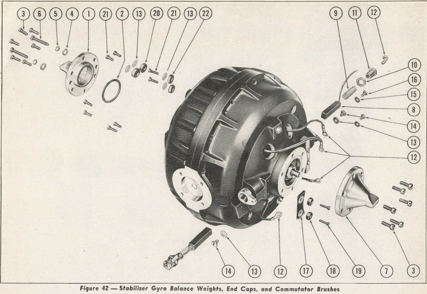
Exploded spacing is not assembled clearance.
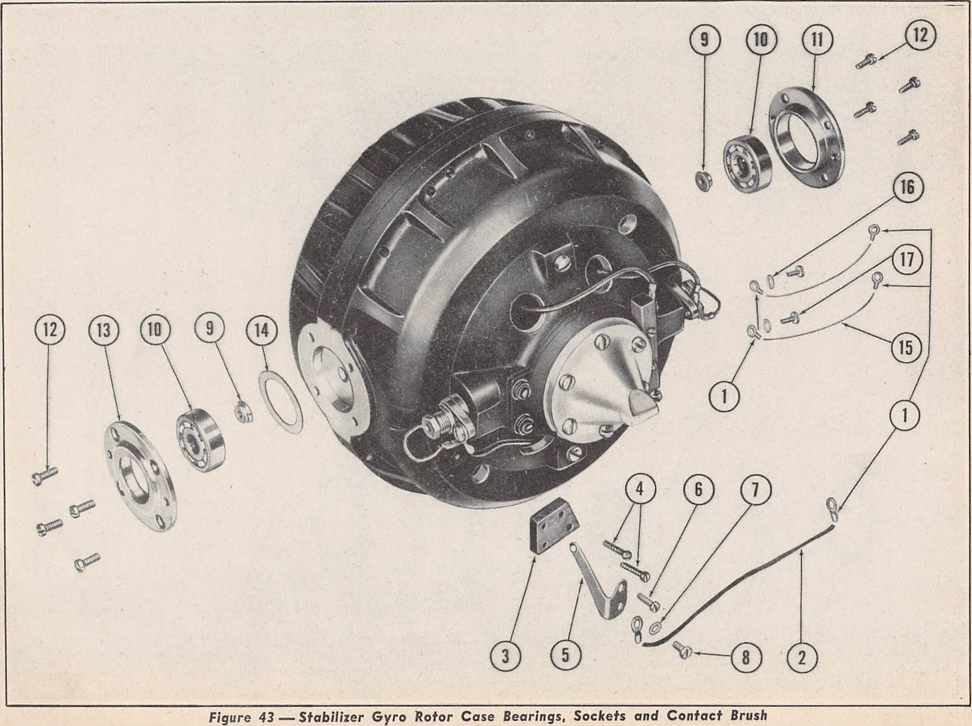
Exploded spacing is not assembled clearance.
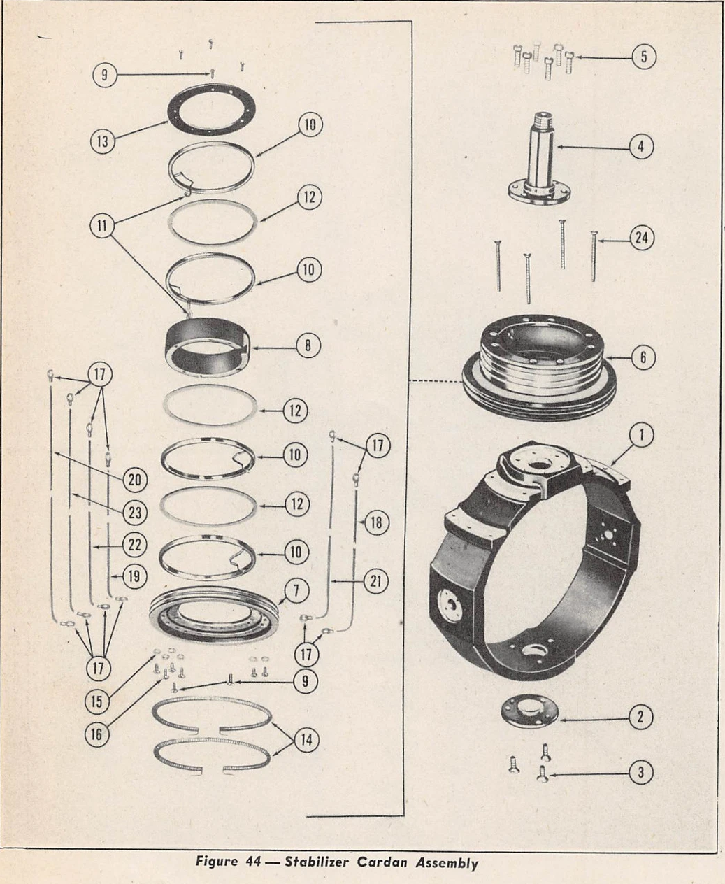
Exploded spacing is not assembled clearance.
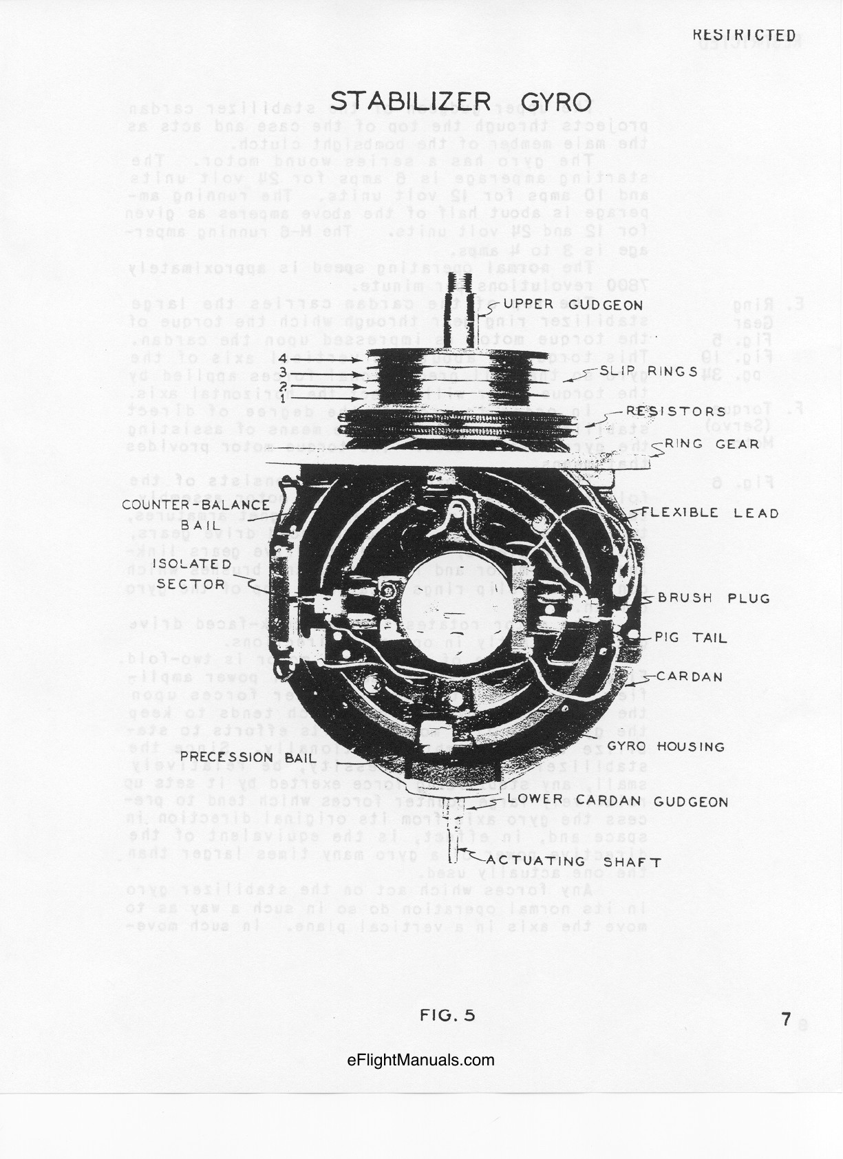
Near-front assembled gyro; check nested widths and all four exposed slip rings. Brush plug pair establishes horizontal case-local clocking; atlas screen diagonals are oblique projections.
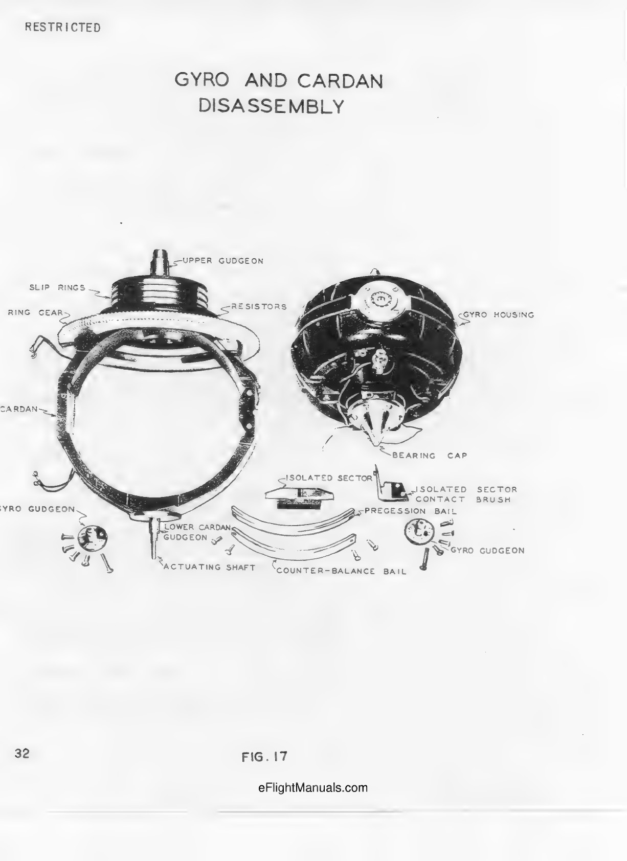
Separate scan of the same stated 1943 revision; disassembly and section topology, not measured dimensions.
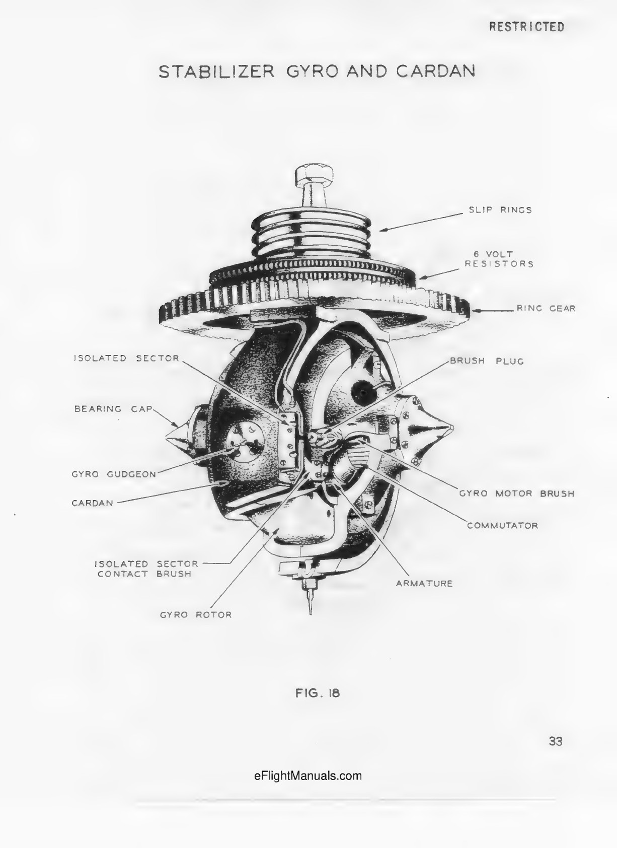
Separate scan of the same stated 1943 revision; disassembly and section topology, not measured dimensions.