Mechanical rate-end computer
A motor-driven disc, movable roller and separate quadrants translating mechanical settings into telescope motion.
Follow the mechanism
The motor drives the disc. Moving the pickup roller outward changes the motion taken from its surface.
The rate quadrant retains its manual setting while the telescope quadrant moves.
Use the relative settings and slowed motion to trace the transmission. The study does not reproduce calibrated scales or precise gear ratios.
Geometry follows the cited drawings and photographs. Unmeasured dimensions remain approximate; exploded spacing reveals existing model groups rather than a prescribed disassembly procedure.
Reference views
Inspect the full sheets as well as detail views. Figure numbers belong to their named document; similar-looking parts may be different variants.
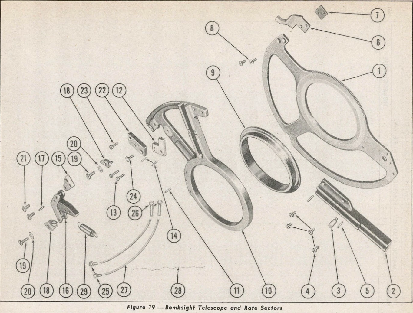
Pierced sector arms, large central bores and camway. Exploded spacing is not installed clearance.
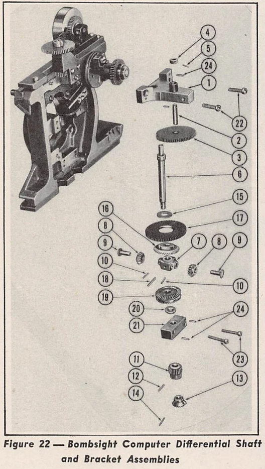
Vertical shaft and gear carrier identity; omitted hidden meshes remain unknown.
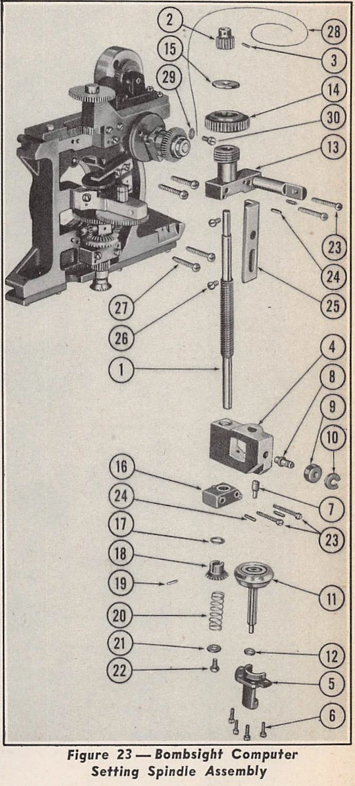
Long setting spindle, sliding carriage and guide bracket.
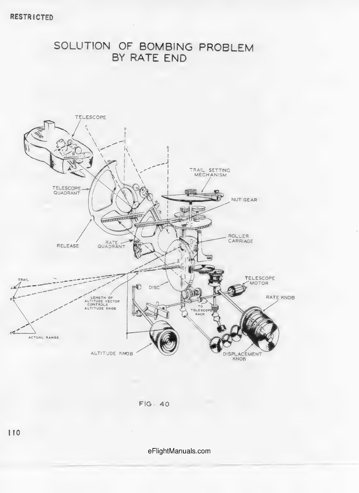
Deliberately spread-out train-of-action schematic. Geometric vectors and release calculations are not reproduced in this educational motion study.
Explicitly states that two intermediate gears were added to uncrowd the drawing. Confirms motor-disc-roller-rack sequence and manual rate quadrant.
Telescope cable and quadrant identity. No numerical flight, aiming or release relationships implemented.