Computer differential shaft and brackets
The coaxial side gears, opposed transverse pinions and carrier, with a two-axis support bridge and separate short shaft and spur gear.
Follow the mechanism
Set the two side-gear inputs and play the motion. Equal inputs carry the pinions around together; opposite inputs spin the pinions while the carrier stays still.
Stop one input to see the carrier combine their motions. Separate the assembly to inspect the pinion pins, shaft fittings and two support brackets.
The isolated geometry follows the parts plate. Its exact installed position and connections within the complete rate end still need confirmation.
A symmetric teaching model. Tooth counts, dimensions and hidden shaft keying remain unverified. The early patent corroborates the differential principle; it does not establish identical production parts or calibrated drive ratios.
Geometry follows the cited drawings and photographs. Unmeasured dimensions remain approximate; exploded spacing reveals existing model groups rather than a prescribed disassembly procedure.
Reference views
Inspect the full sheets as well as detail views. Figure numbers belong to their named document; similar-looking parts may be different variants.
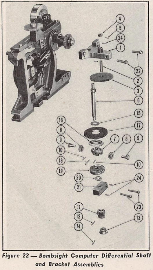
Fig22 thumbnail lacks the exposed differential. Exploded parts show upper/lower brackets1/21, main shaft6, offset short shaft2/gear3, side members16/19, carrier7, opposed pinions8 with pins9, larger spur17 and lower fittings11/13. Names remain descriptive.
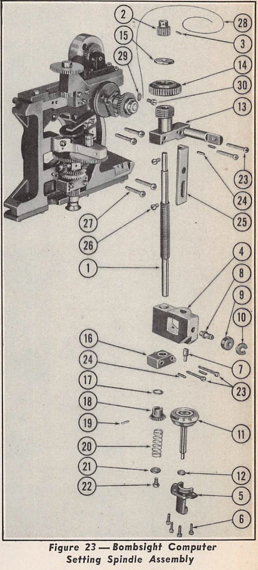
The exploded parts belong to the separate setting spindle, but its thumbnail visibly retains the assembled Fig22 differential. Correspondence rests on paired bridge/block supports, opposed carrier pinions, lower spur/bevel fittings and the distinct rightward shaft2 stub. It corroborates offset axes and compact nesting, not exact distances or drive keying.
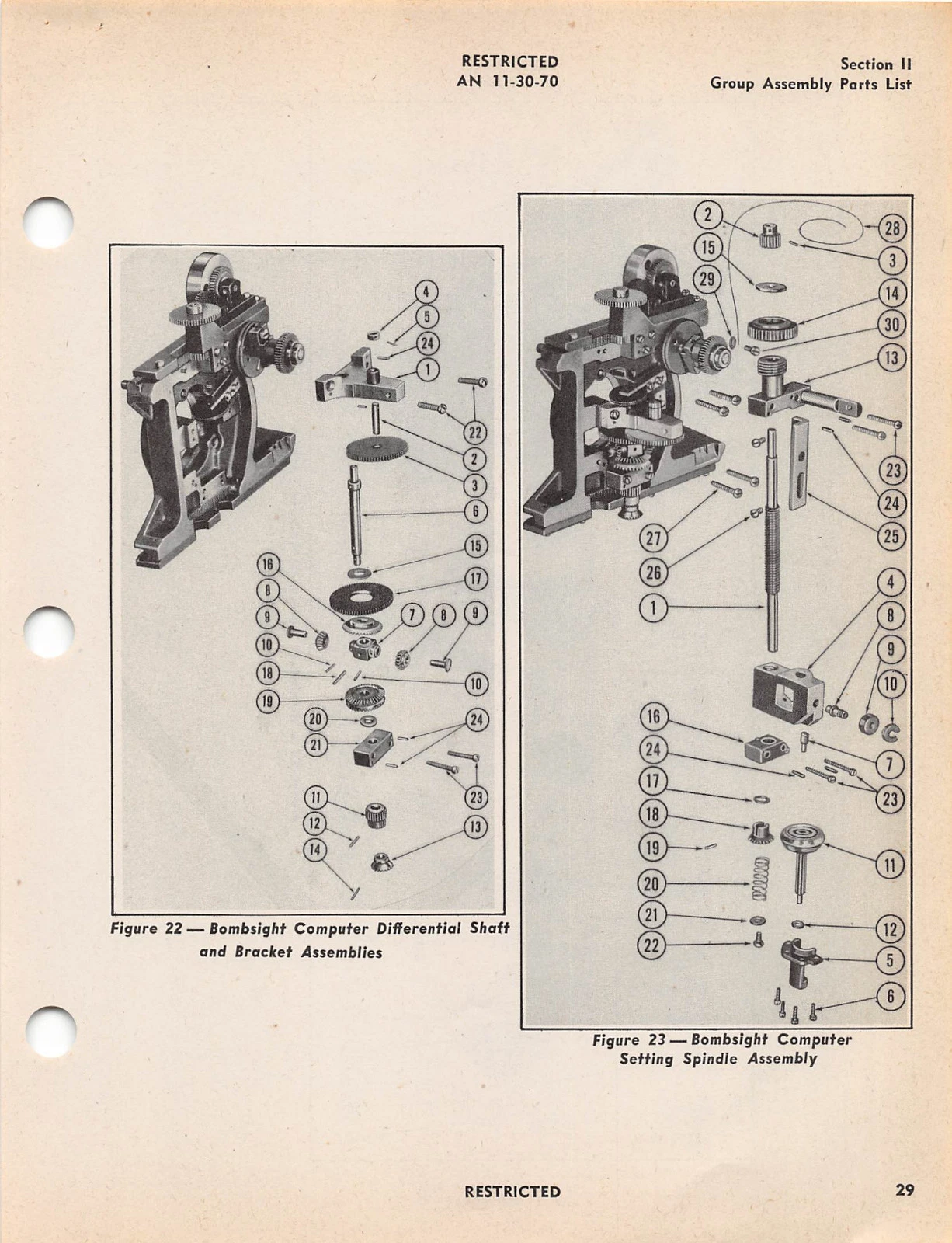
Untouched source; Fig22 differential shaft/brackets and assembled thumbnail at left. Fig23 is a separate setting spindle assembly, not additional differential parts.
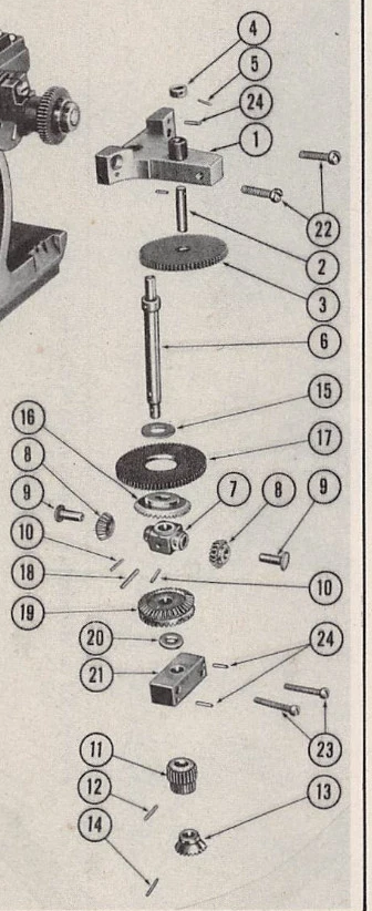
Clear exploded coaxial gear/carrier stack. No dimensions or tooth counts supplied.
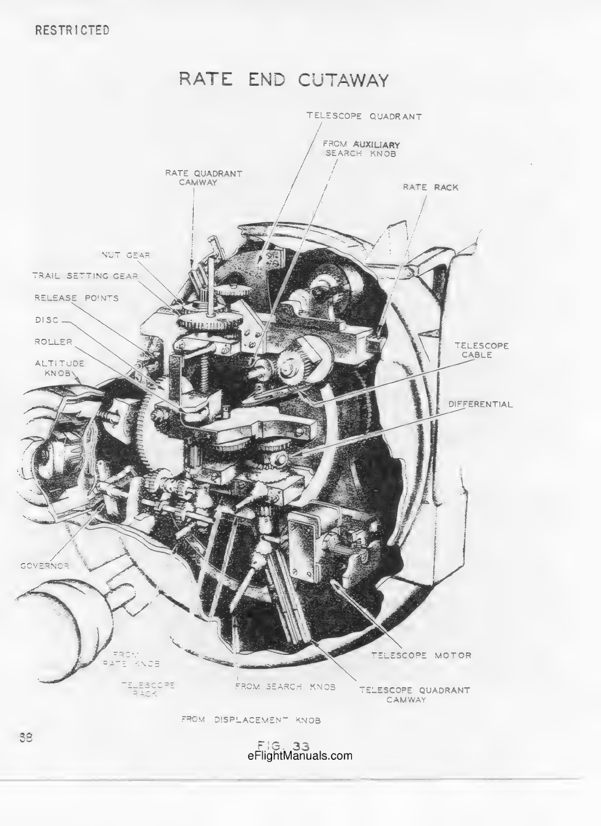
Differential identification and installed computer-half context; not a registered isolated-assembly view.
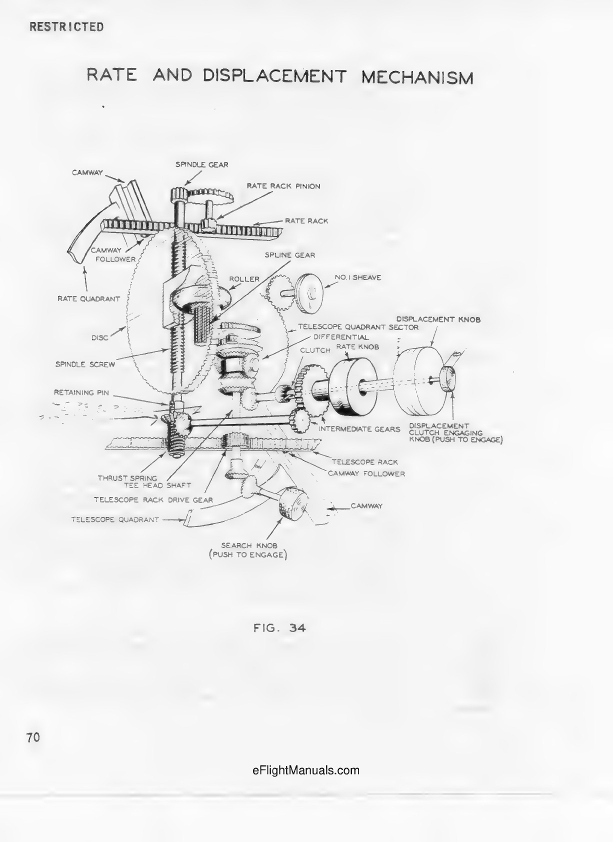
Rate/displacement train schematic identifies differential function; not installed distances or historical ratio calibration.