Altitude knob assembly
The knob, graduated setting mechanism and breaker-point adjustment associated with the rate motor’s governed drive.
Follow the mechanism
The historical altitude setting changes the motor regulation mechanism.
Compare the carrier, spring and contact placement with the original drawing; the reproduced scale is not a calibrated flight instrument.
Geometry follows the cited drawings and photographs. Unmeasured dimensions remain approximate; exploded spacing reveals existing model groups rather than a prescribed disassembly procedure.
Reference views
Inspect the full sheets as well as detail views. Figure numbers belong to their named document; similar-looking parts may be different variants.
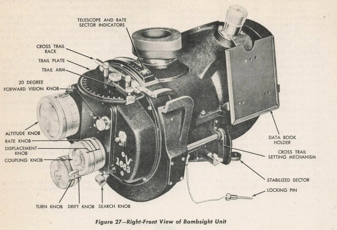
Alternate installed exterior view labels altitude knob. Does not expose spring internals; variant correspondence unconfirmed.
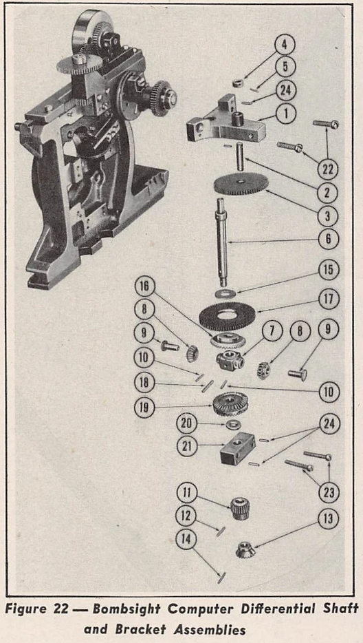
Inspected computer packet candidate. Differential shaft is a different assembly, not an alternate altitude-knob interior angle.
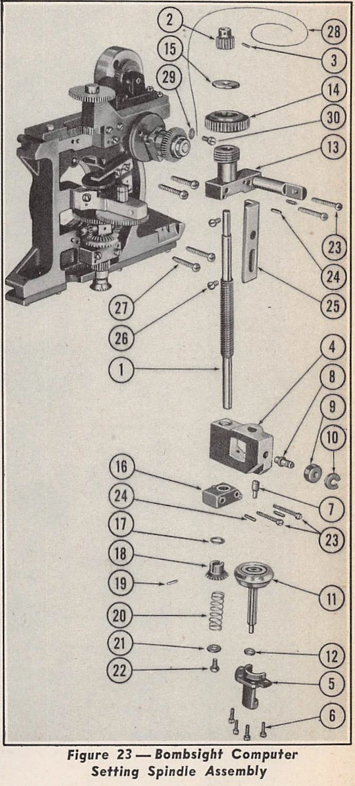
Inspected computer packet candidate. Setting spindle is a different assembly; spring cannot establish altitude spring geometry.
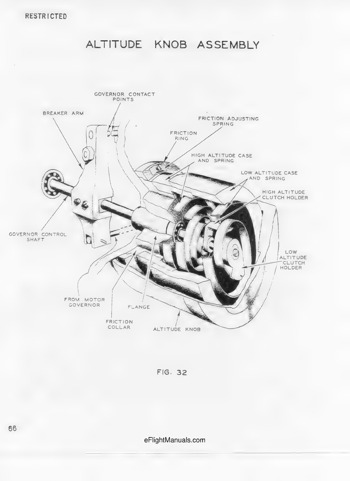
Printed page 66. Oblique cutaway, not exploded. Near upper walls removed to expose concentric spring cases and clutch holders. Dimensions not given.
Printed page 65. Two spring cases and torque coupling to breaker arm.
Printed page 67. Cases nest over friction collar; three adjustable screws per case; two leaf springs, above and below friction ring.