Rate-end motor half
The parallel-wound motor, centrifugal governor, breaker arm and transmission of the motor half.
Follow the mechanism
The armature turns within the fixed field. The governor responds to shaft rotation.
Governor movement draws the breaker arm to interrupt the armature circuit; the regulator restores the contact as speed falls.
The motion controls slow these relationships for inspection.
The opening arrangement follows Fig. 45’s disassembly spread. Additional explode spacing is illustrative, not installed clearance.
Geometry follows the cited drawings and photographs. Unmeasured dimensions remain approximate; exploded spacing reveals existing model groups rather than a prescribed disassembly procedure.
Reference views
Inspect the full sheets as well as detail views. Figure numbers belong to their named document; similar-looking parts may be different variants.
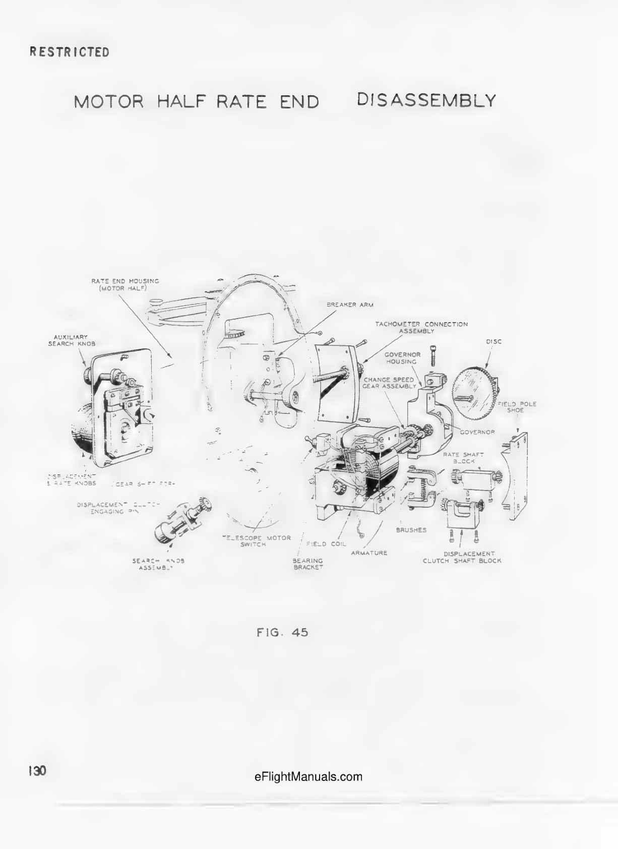
Primary source spread; motor half housing, knob mounting plate, motor, governor, disc and detached shaft blocks. Geometry follows this disassembly state, not installed spacing.
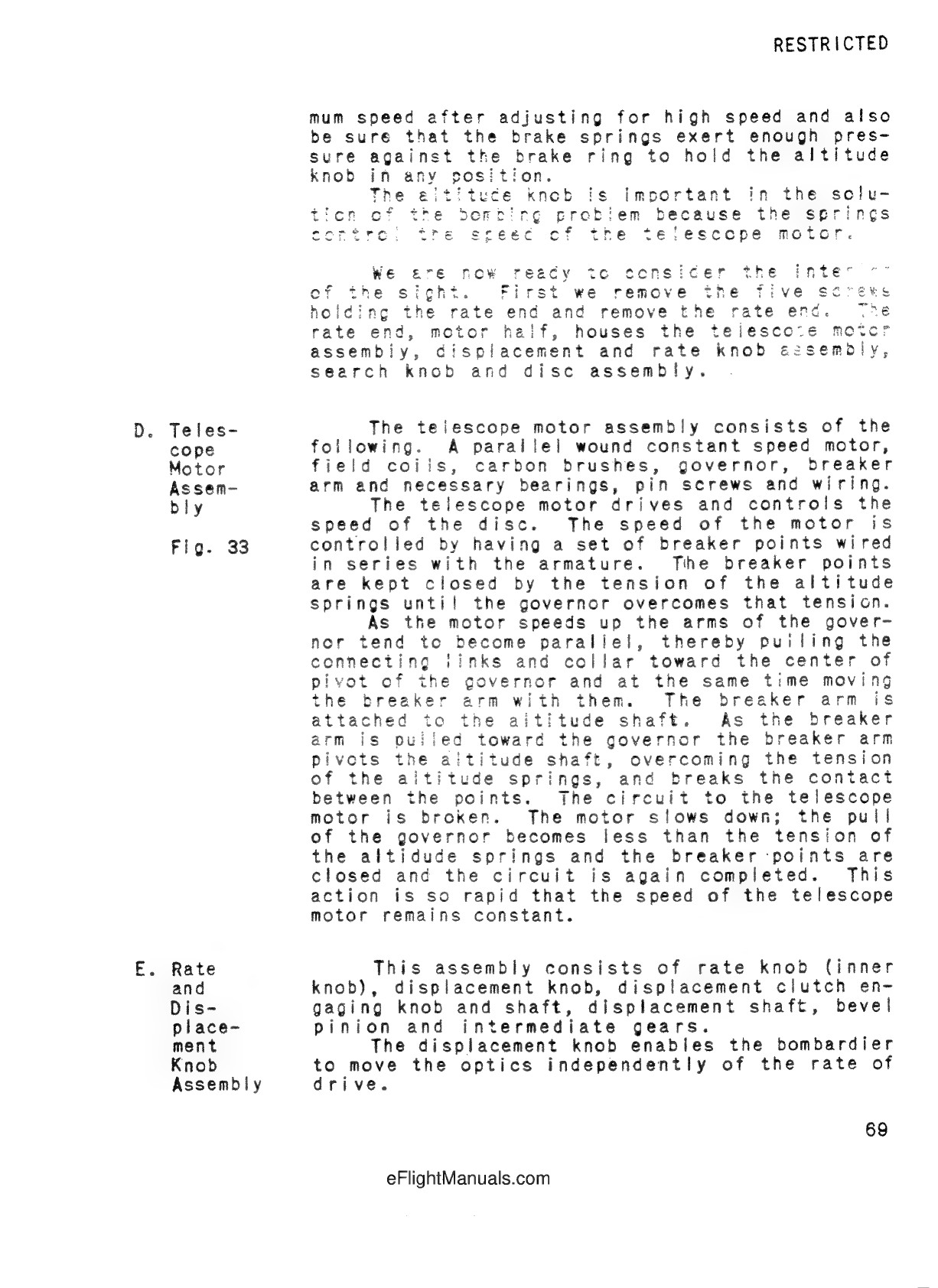
Parallel-wound telescope motor; breaker points in series with armature. Governor collar pulls breaker arm against altitude spring tension; points open and reclose to regulate speed. No calibrated operating values reproduced.
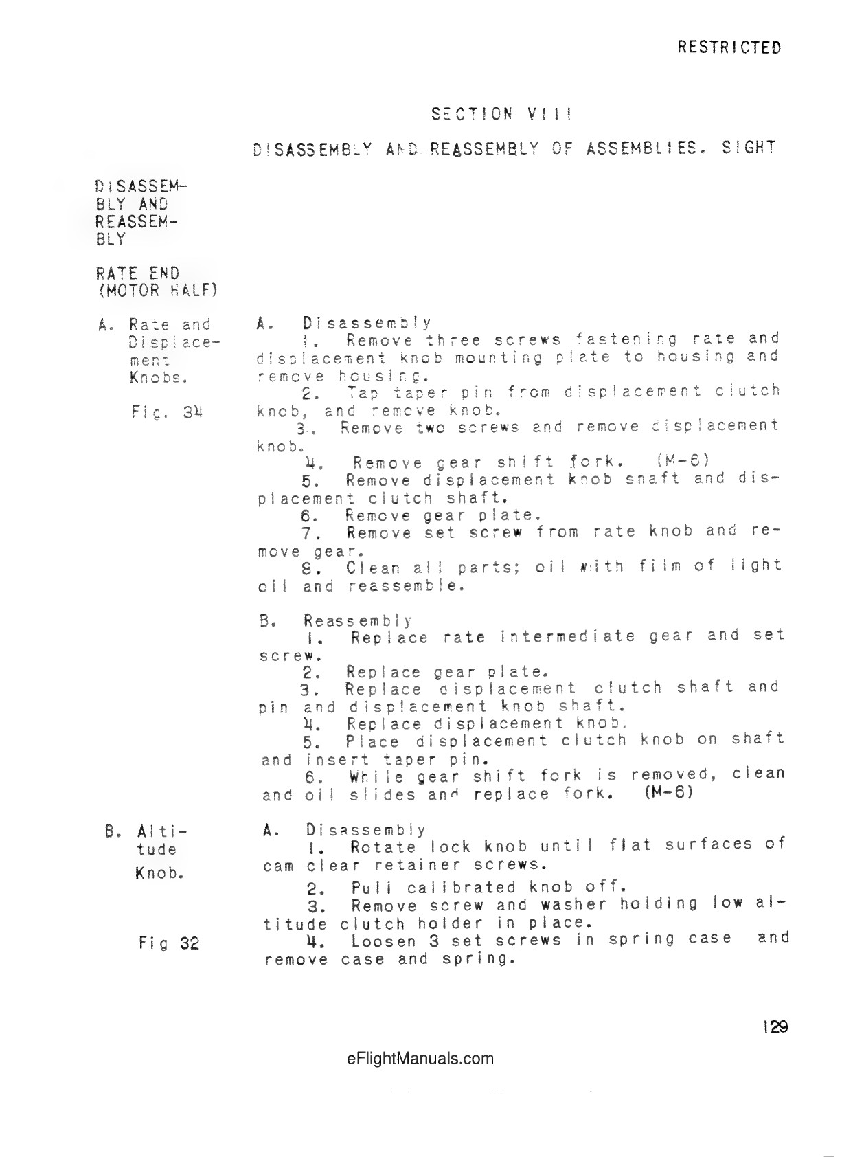
Rate/displacement knob and mounting plate disassembly; M-6 gear shift fork explicitly variant-dependent.
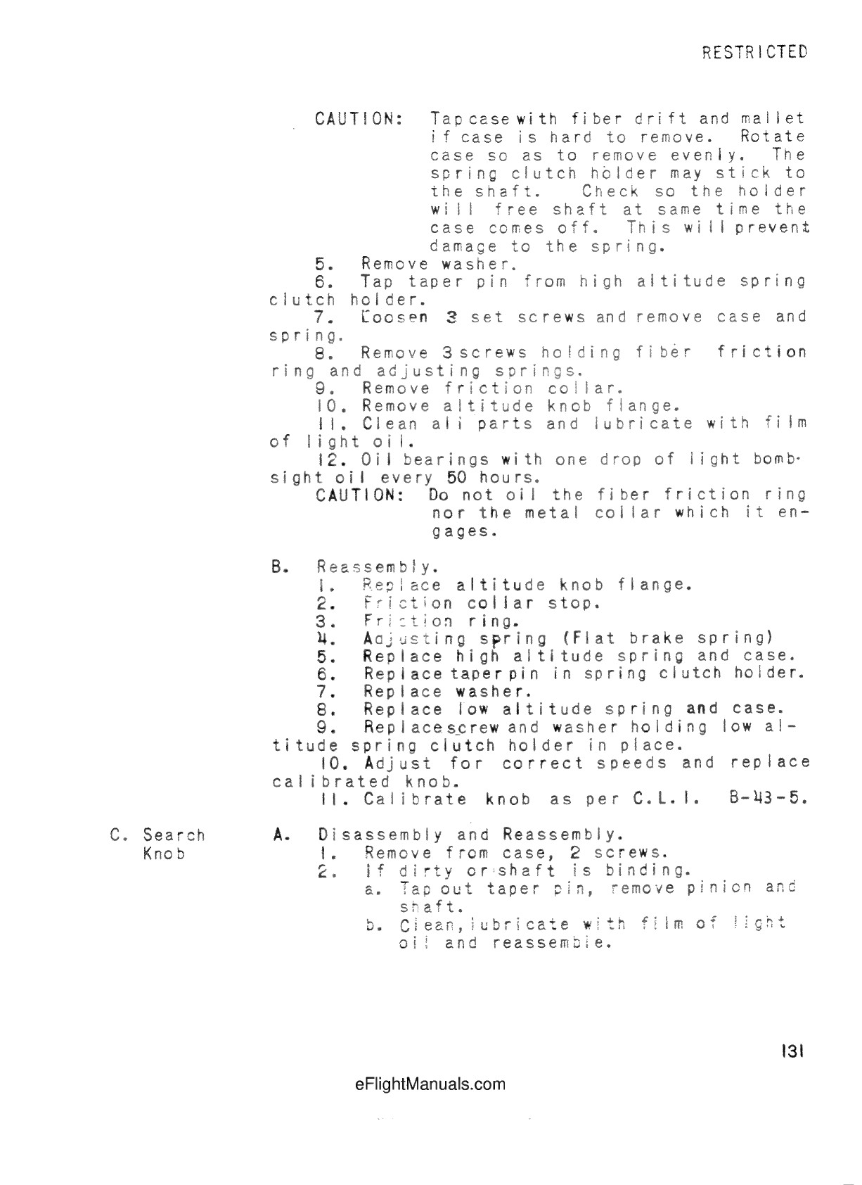
Search knob removed by two screws, pinion on tapered pin.
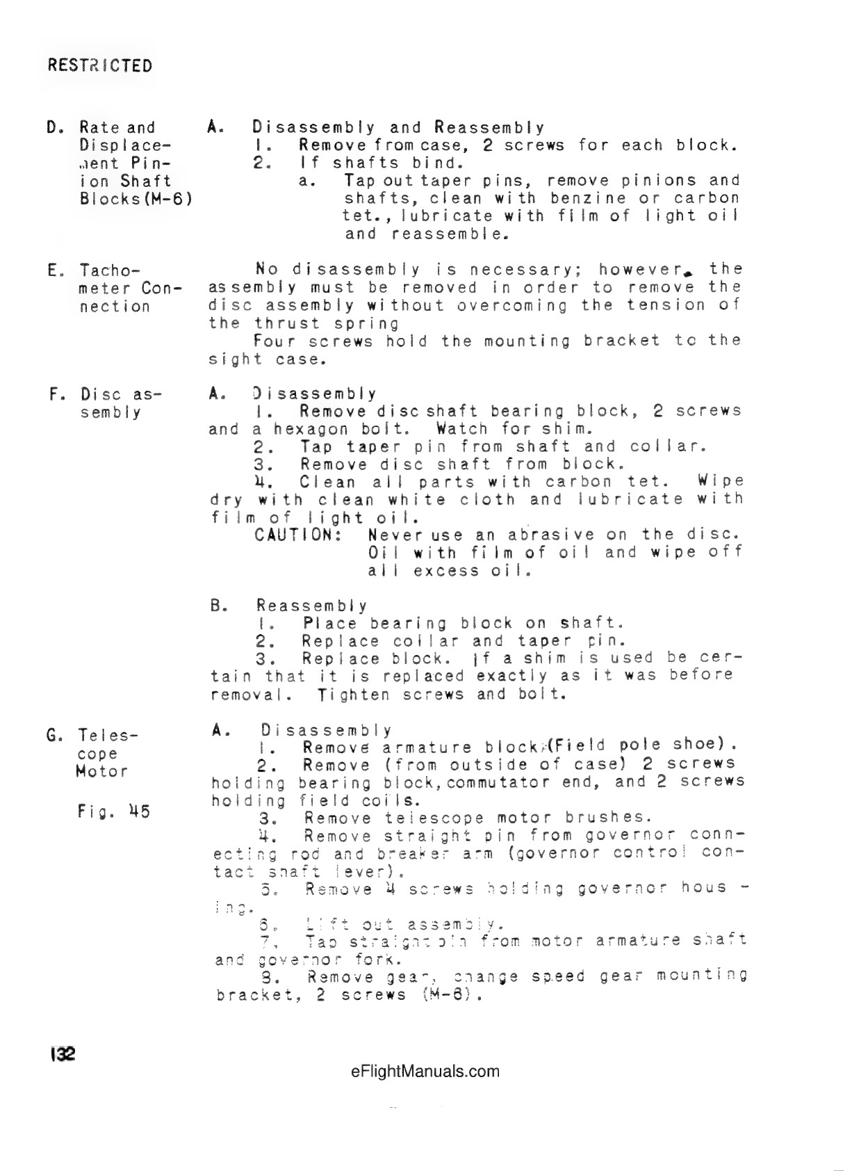
Confirms tachometer bracket four screws, field pole shoe, commutator-end bracket, brushes, governor link and housing. Shaft blocks explicitly M-6. Change-speed bracket marked M-3 here.
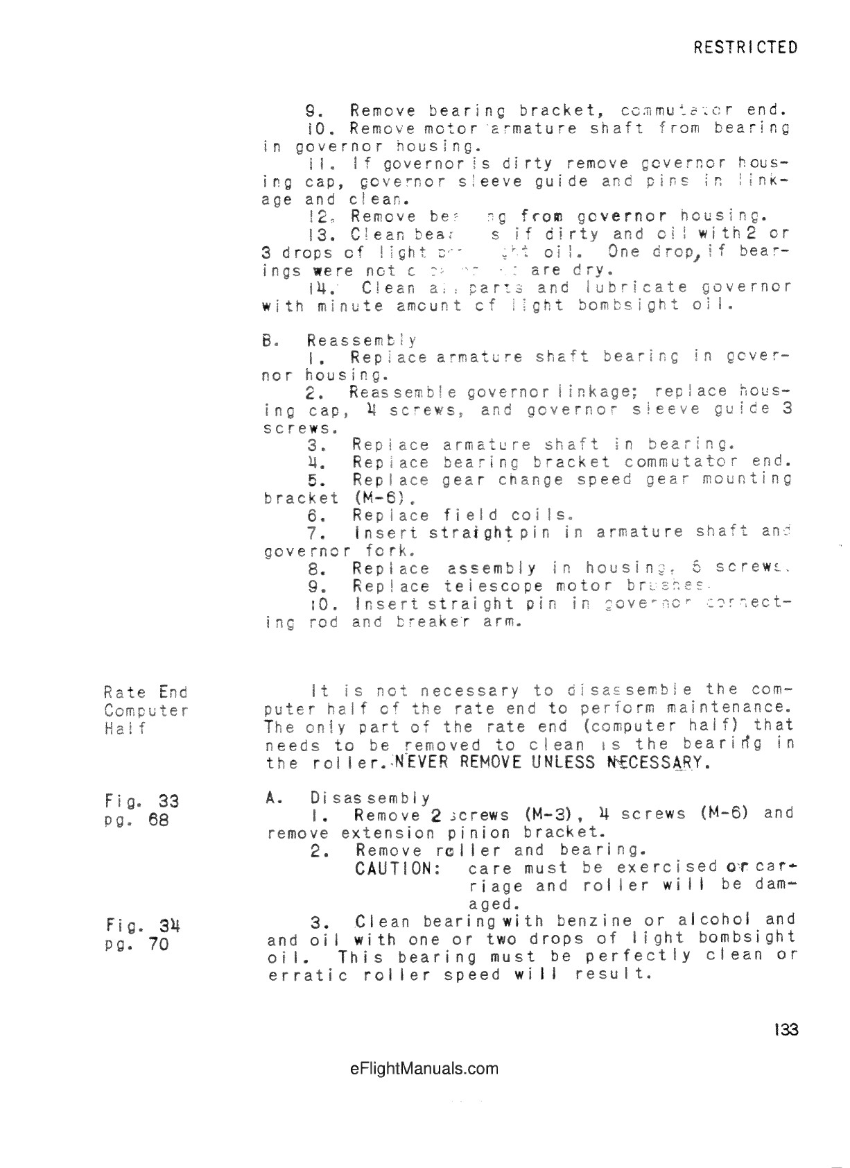
Governor sleeve guide, bearing and armature relationships. Change-speed bracket marked M-6 here, unlike preceding page; variant correspondence unresolved.
Further reference sources
- War Department training film 1-871, 1943, AWM F02526 ↗
- Childress County Heritage Museum CCHM_42, UNT Portal to Texas History ↗
- Glenn’s Computer Museum, separated motor half, exact modification unverified ↗
- Bombsight Wiring Diagram, printed Fig4-40, marginal5.11.10-1-143; publication/date unresolved ↗
- T.O.11B41-2-2-1, 15Aug1958, Change1 27Feb1967 ↗