Rate and displacement mechanism
Separate rate and displacement controls arranged around the disc-and-roller transmission.
Follow the mechanism
Rate adjustment shifts the roller across the rotating disc, changing the motion taken from its surface.
Displacement changes telescope position independently. Coaxial controls therefore need separate pivots.
Geometry follows the cited drawings and photographs. Unmeasured dimensions remain approximate; exploded spacing reveals existing model groups rather than a prescribed disassembly procedure.
Reference views
Inspect the full sheets as well as detail views. Figure numbers belong to their named document; similar-looking parts may be different variants.
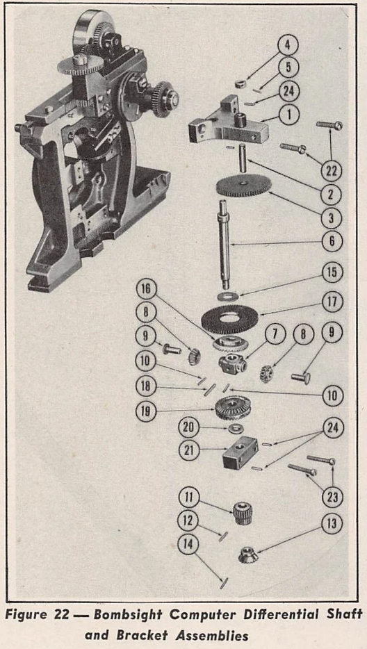
Bracket/vertical shaft/differential carrier topology. Exploded spacing is not installed clearance.
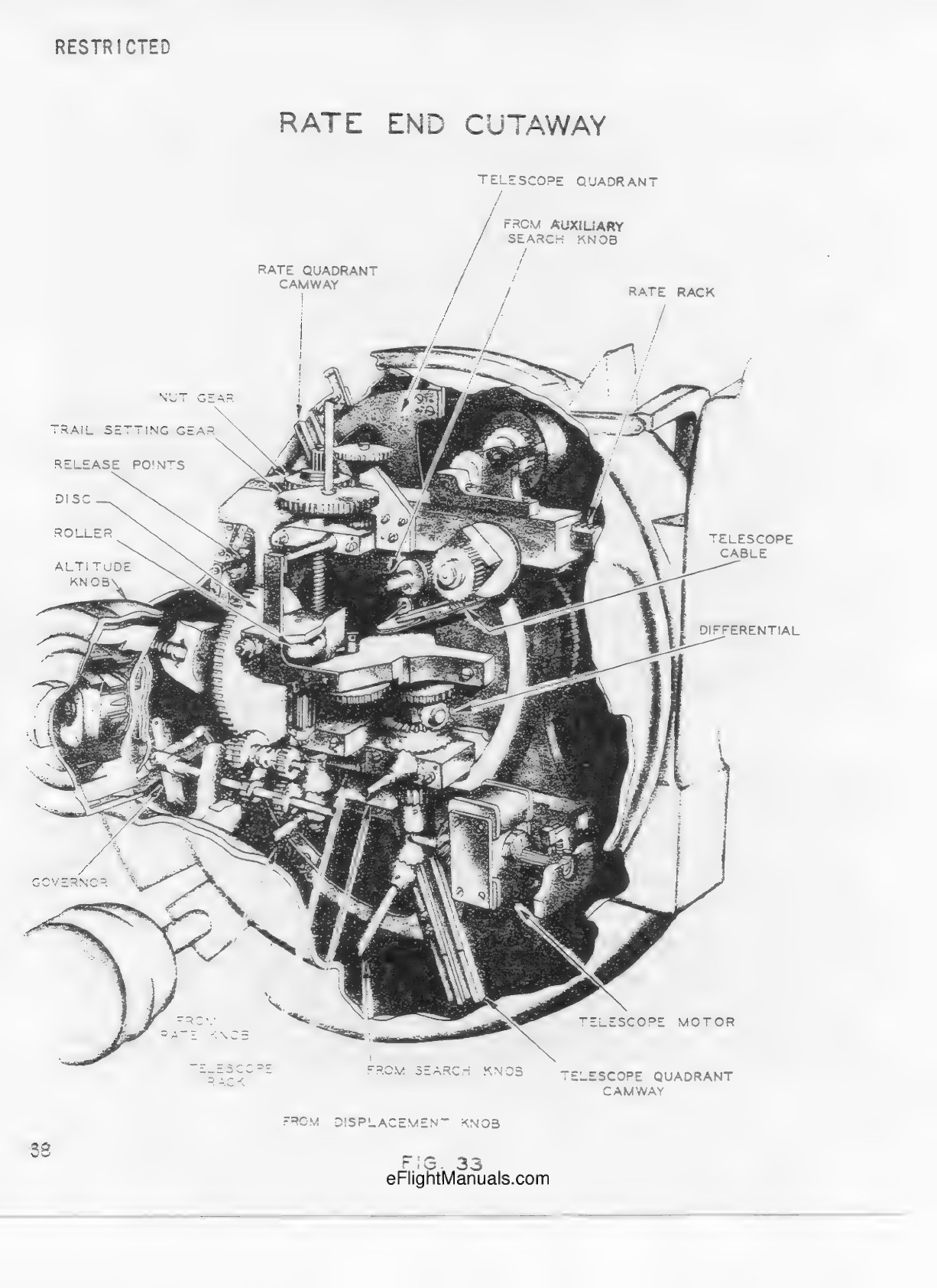
Installed rate end with near housing removed. Primary spatial reference; gear counts and hidden mesh details are not legible.
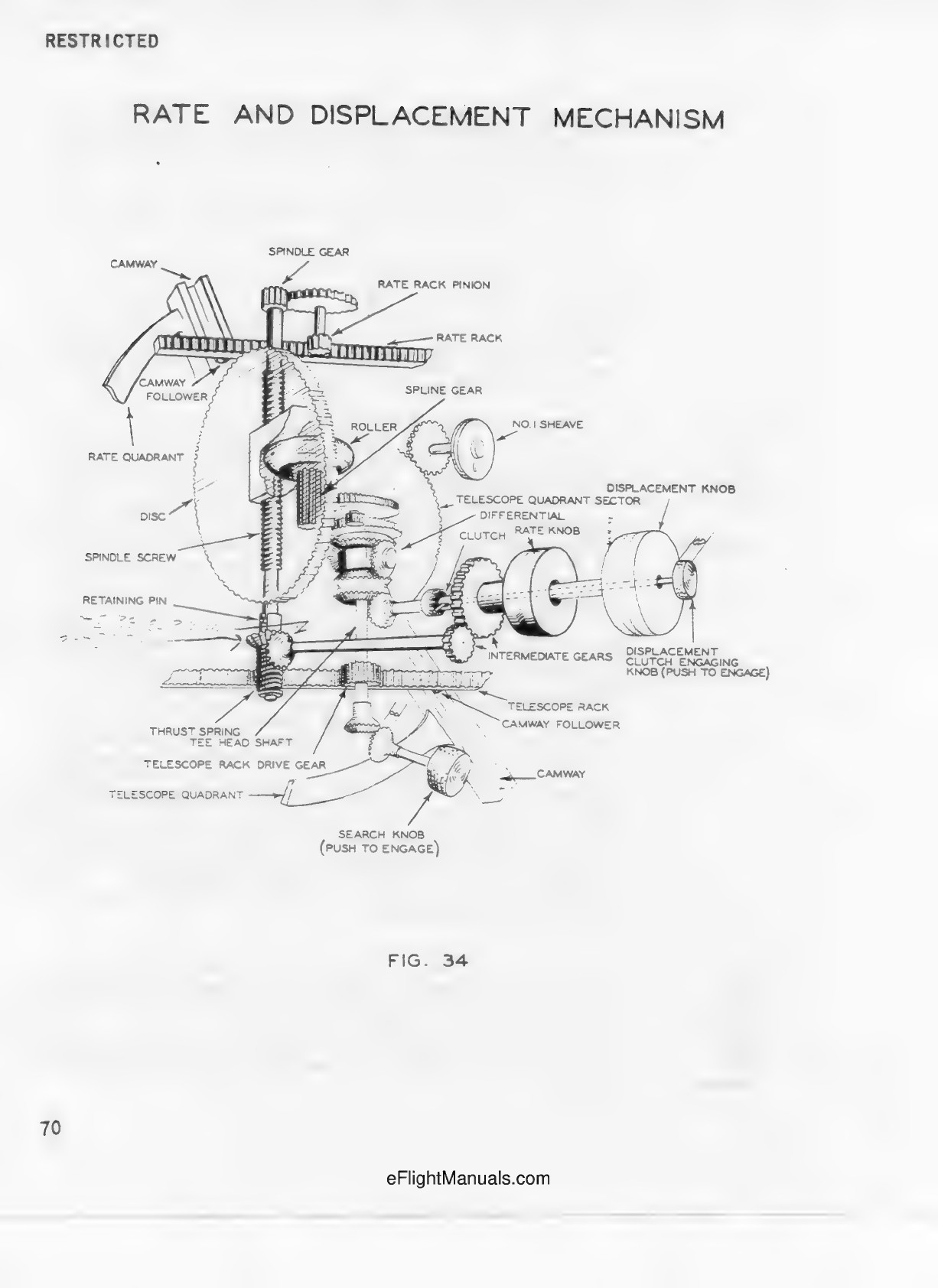
Separate exposed mechanism schematic. Used for component identity and disc/roller topology, not a matching installed camera.
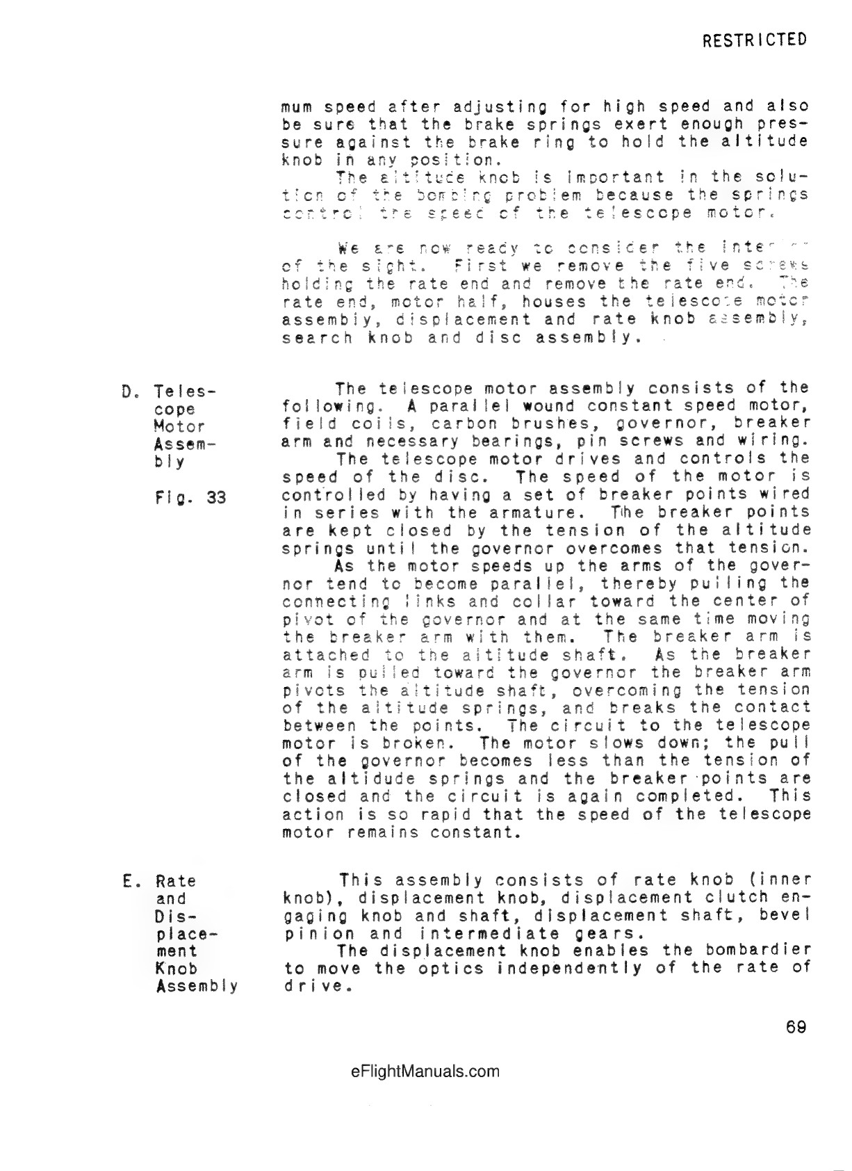
Identifies rate-end contents and motor/governor.
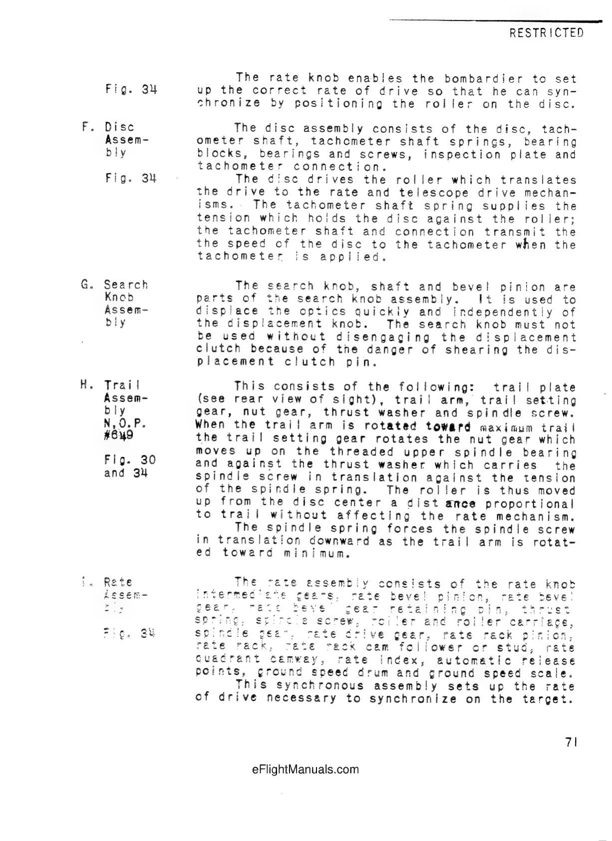
Identifies disc, roller, spindle and trail assembly relationships. No operating calibration implemented.
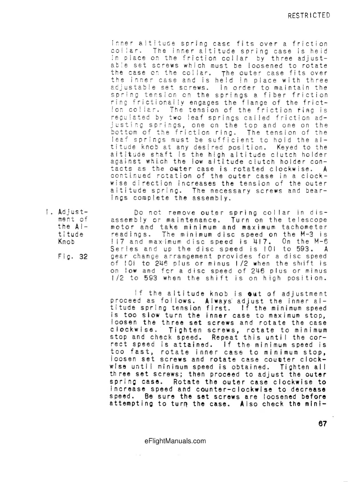
Altitude case context; historical variants prevent importing operating values.
Further reference sources
- University of Queensland Physics Museum, object2459 ↗
- National Air and Space Museum, Smithsonian Institution, objectA19601945000 ↗
- USAAF Bombardiers Information File, March1945, BIF6-1-1 ↗
- Childress County Heritage Museum CCHM_42, UNT Portal to Texas History ↗
- War Department training film1-871, 1943, AWM F02526, elapsed05:30 ↗
- T.O.11B41-2-2-1, 15Aug1958, Change1 27Feb1967 ↗