Precession leveling knobs
The fore-and-aft and lateral leveling controls, with their quick-setting and constant-torque knob pairs, springs and friction contacts.
Follow the mechanism
The fore-and-aft control acts through a friction disc on the gyro housing; the lateral control uses a friction cone disc on the cardan.
The smaller outer knobs provide quick setting and the larger inner knobs provide constant torque. Springs limit applied force and return the controls outward.
The manual describes the bubble following the top of the knob when the gyro is running.
Geometry follows the cited drawings and photographs. Unmeasured dimensions remain approximate; exploded spacing reveals existing model groups rather than a prescribed disassembly procedure.
Reference views
Inspect the full sheets as well as detail views. Figure numbers belong to their named document; similar-looking parts may be different variants.
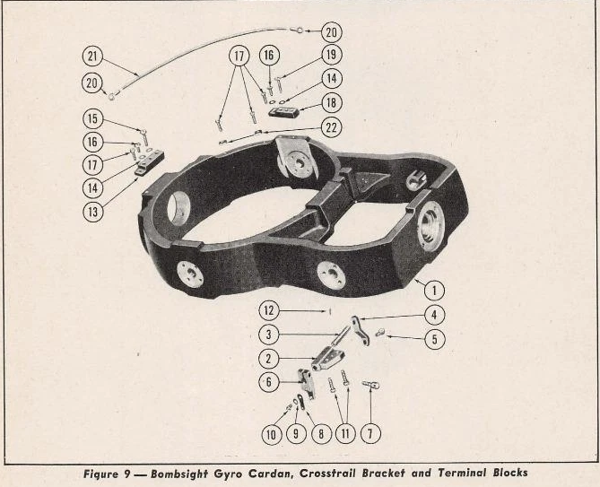
Supports deep curved cardan rail and gudgeon seats; not a leveling-knob parts list.
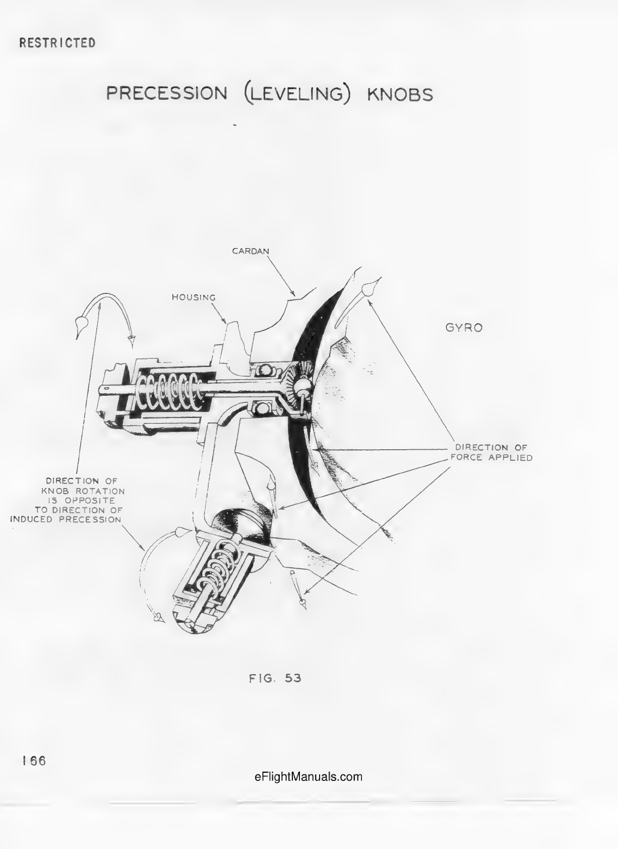
Printed p.166. Cutaway of the two spring-loaded shafts and friction contacts, housing, cardan and partial gyro. Section edges are not physical open housings.
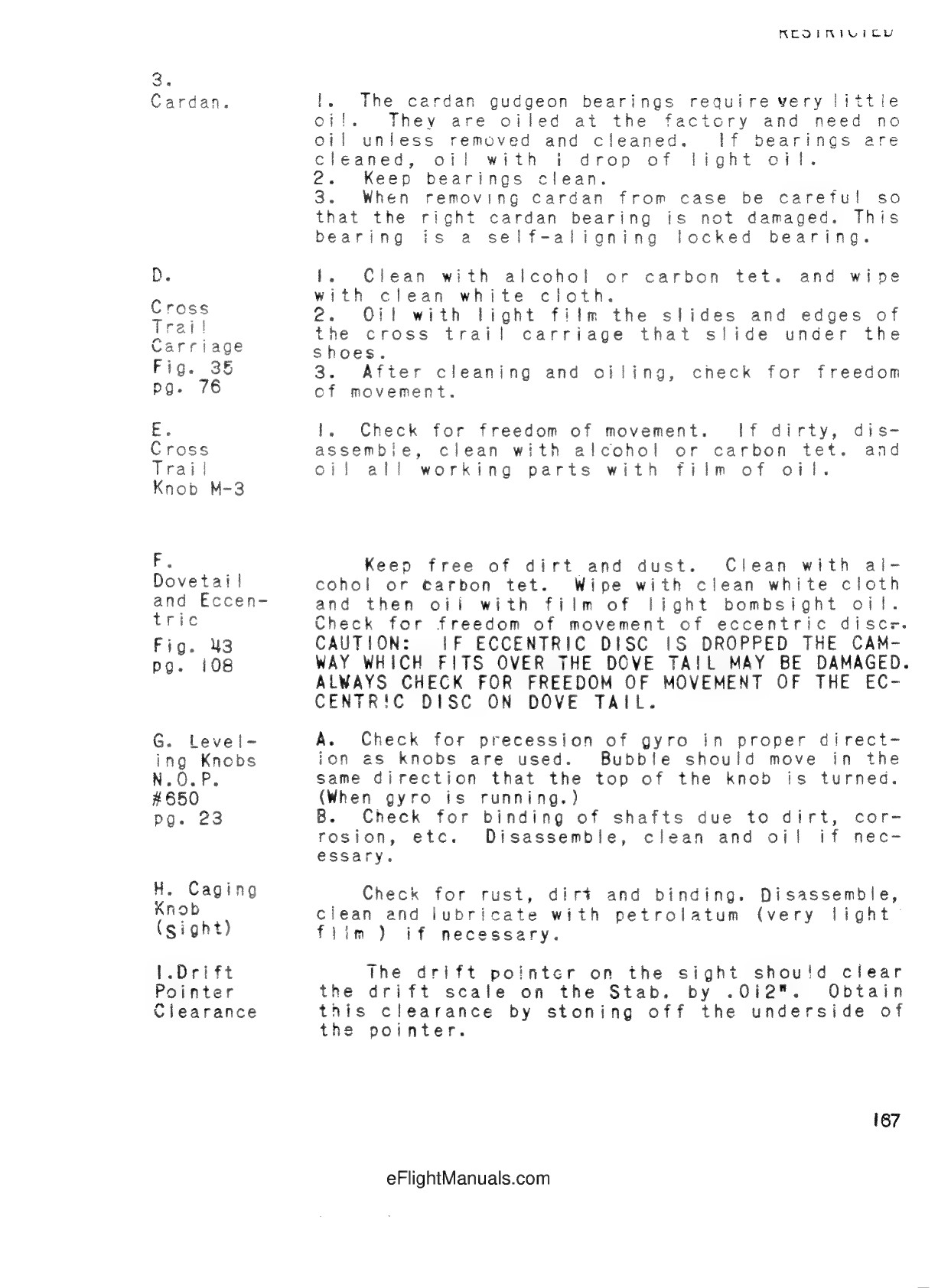
Printed p.167, G. Leveling Knobs. Bubble motion follows the top of the knob with gyro running. Caging knob is a separate mechanism.
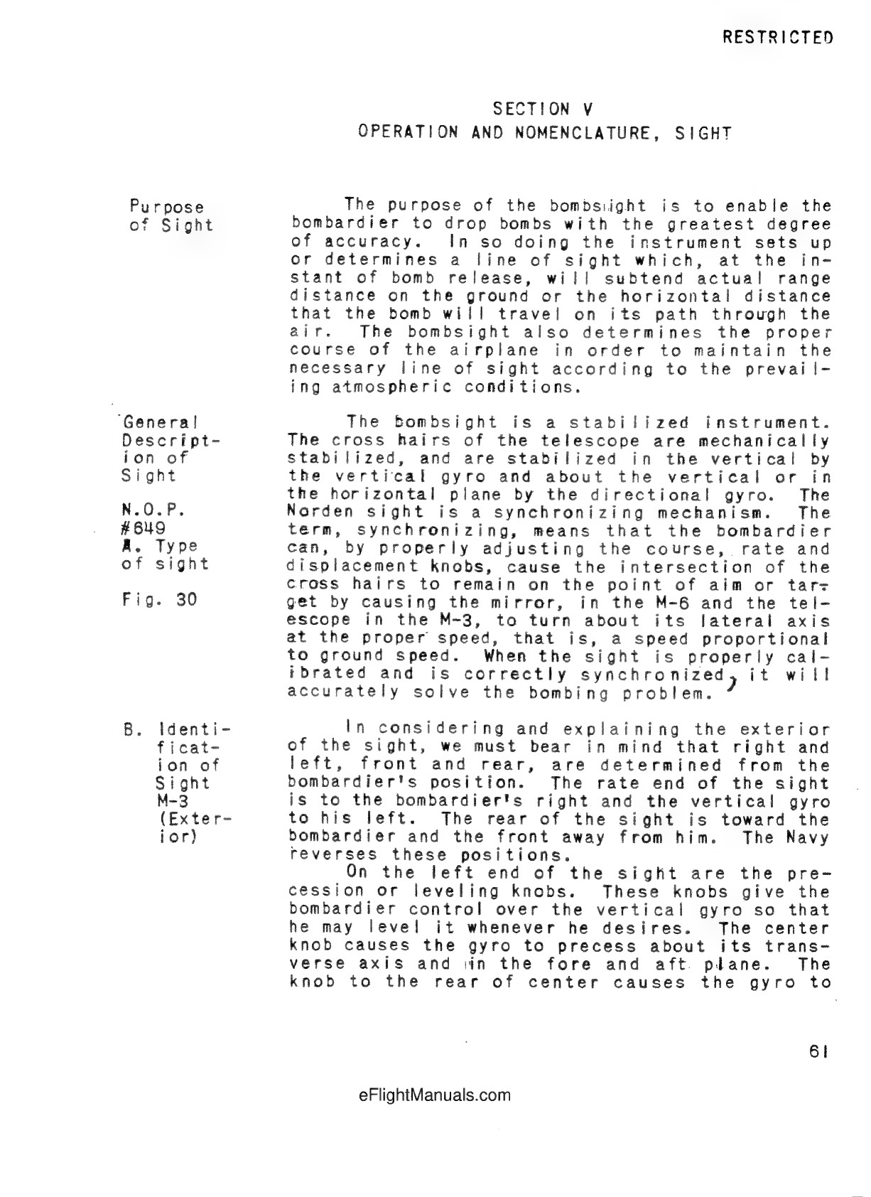
Printed p.61. Center knob controls fore-and-aft precession; rear knob controls lateral precession. Not the stabilizer precession motor.
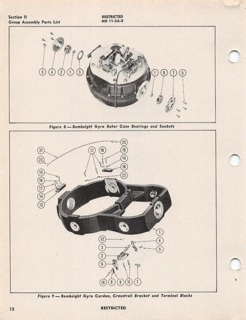
Original sheet, p.12. Sight gyro and cardan form only; exploded spaces do not specify installed contact gaps.
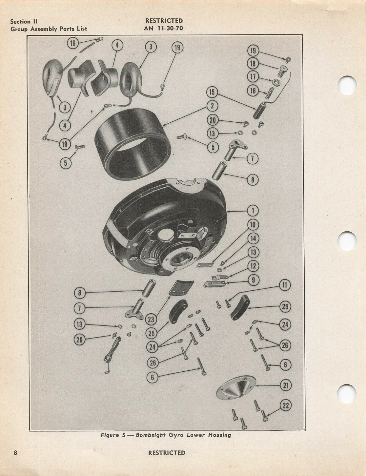
Original sight gyro lower housing sheet. Distinct from stabilizer gyro bails.