Telescope cable and sheaves
The installed cable path for the M-4-and-up arrangement, with five sheaves, guided passages and secured eyelets.
Follow the mechanism
The cable starts at the secured No. 5 eyelet, passes through the front cradle gudgeon and follows sheaves No. 4 and No. 3.
It passes through the right cardan gudgeon, around No. 2 and No. 1, and terminates at the eyelet and eccentric adjustment.
The seven circled numbers in Fig. 51 identify installation details, not seven sheaves. Open the original page for the complete sequence.
This is an assembled topology reconstruction from several details. Exact sheave clearances, cable diameter and groove profiles remain inferred.
Geometry follows the cited drawings and photographs. Unmeasured dimensions remain approximate; exploded spacing reveals existing model groups rather than a prescribed disassembly procedure.
Reference views
Inspect the full sheets as well as detail views. Figure numbers belong to their named document; similar-looking parts may be different variants.
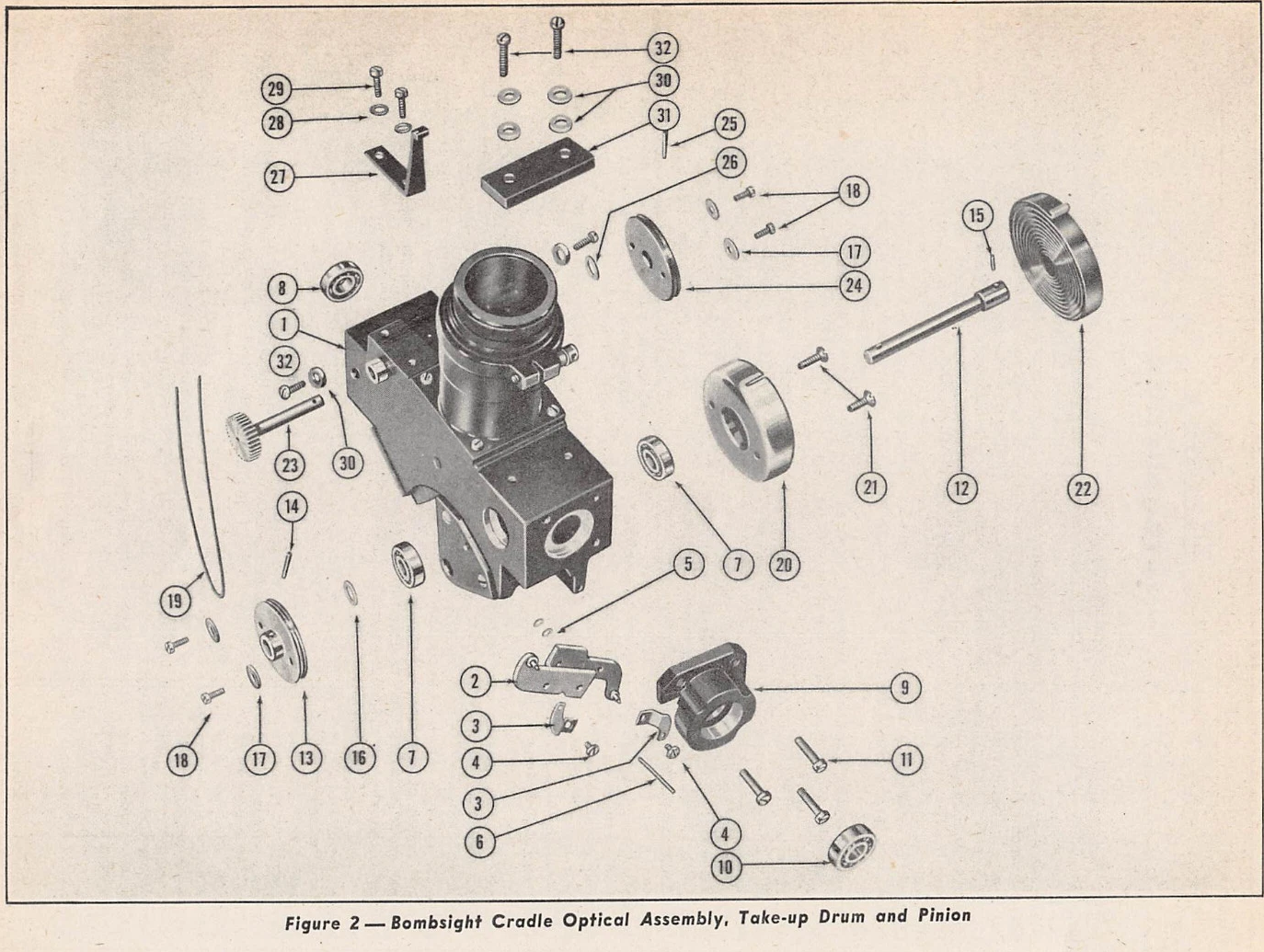
Atlas copy of original parts sheet retained for identity check. Related revision only.
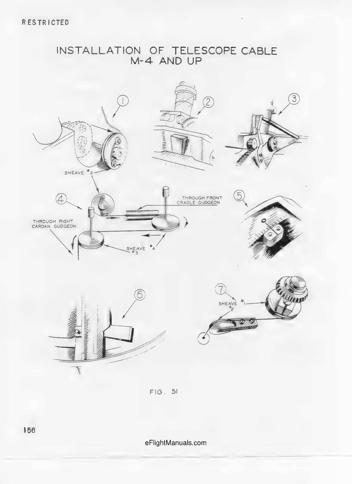
Printed p.156. Seven separate installation details, not seven sheaves. Detail4 establishes cradle gudgeon, sheaves5/4/3 and right cardan gudgeon; detail7 establishes sheaves2/1. No global installed projection or dimensions.
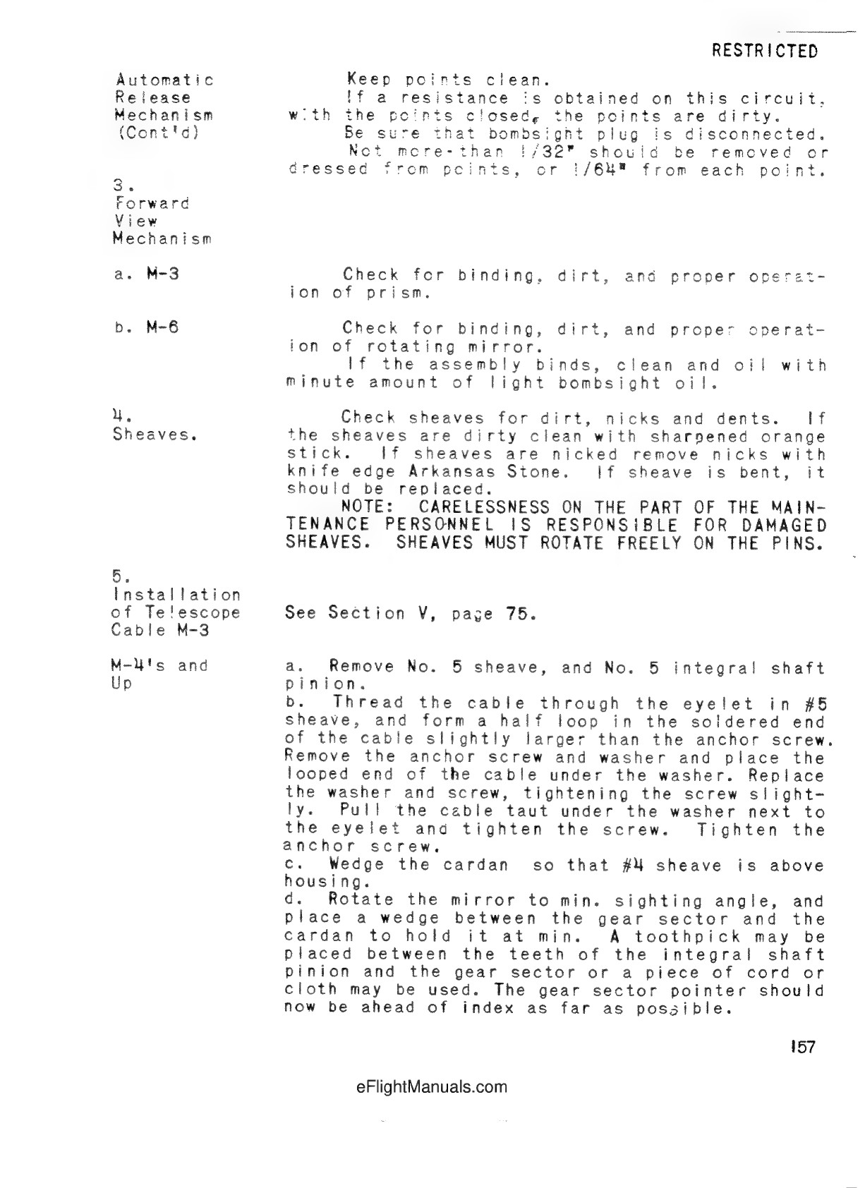
Printed p.157. M-4 and up steps a-d. Soldered cable half loop secured under number5 anchor-screw washer, eyelet and adjacent washer; mirror sector temporarily wedged.
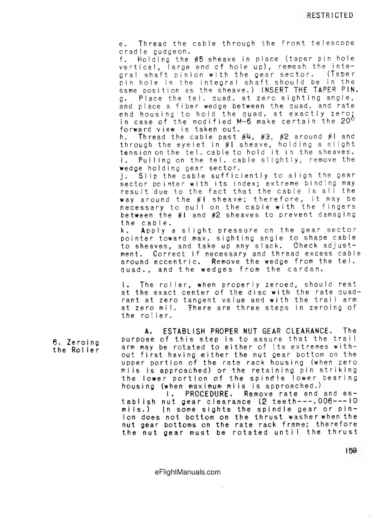
Printed p.159 steps e-k. Through front cradle gudgeon, remesh number5 integral shaft pinion and insert taper pin; past4/3/2 around1 and through eyelet, excess around eccentric. Roller zeroing begins below.
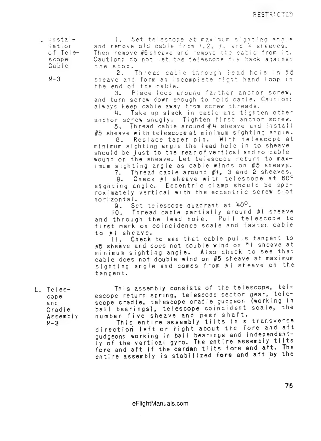
Printed p.75 explicitly M-3. Separate screw and angular adjustment procedure; tangent and no-double-winding checks. Not a source for M-4 adjustment values.
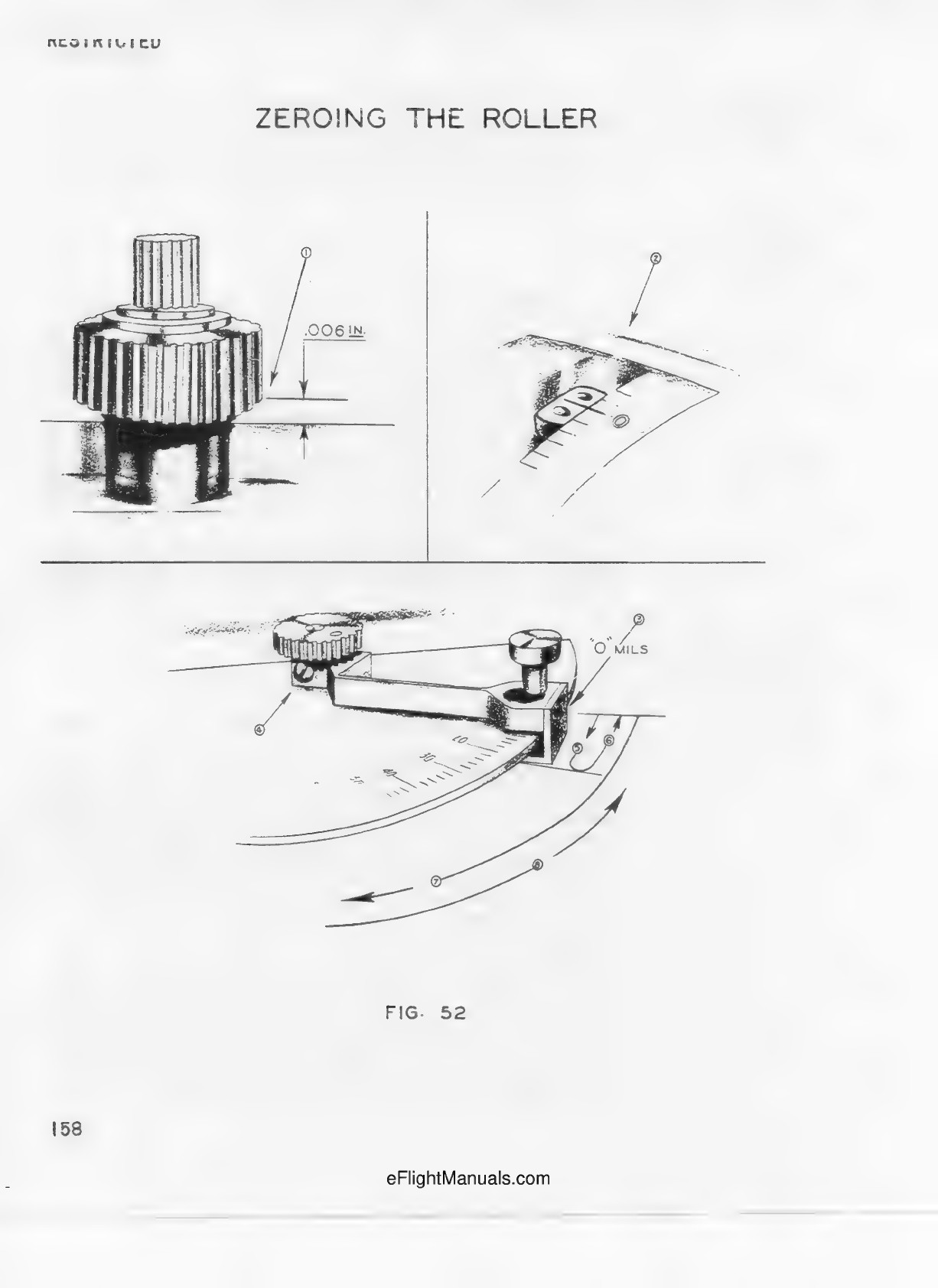
Printed p.158 ZEROING THE ROLLER. The .006 IN figure is nut-gear clearance, NOT cable or sheave dimension.