Sight end-cover assembly
The curved end cover, central bearing support and internal ribs closing the gyro end.
Follow the mechanism
The cover can be removed independently of the upper and lower housing halves.
Explode the bearing support to see its relationship to the curved cover.
Geometry follows the cited drawings and photographs. Unmeasured dimensions remain approximate; exploded spacing reveals existing model groups rather than a prescribed disassembly procedure.
Reference views
Inspect the full sheets as well as detail views. Figure numbers belong to their named document; similar-looking parts may be different variants.
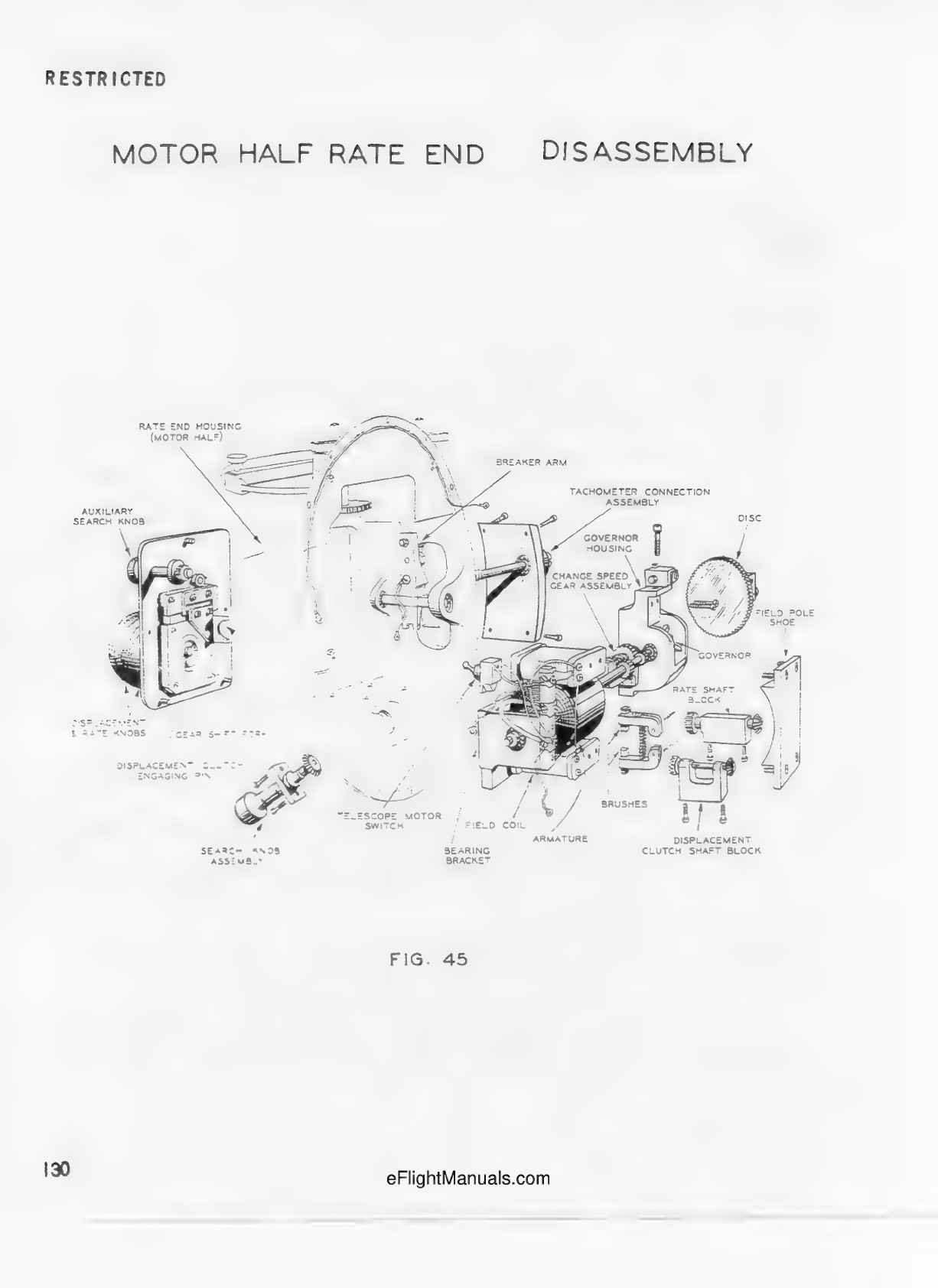
Rate-end motor half and separate shafts; shared motor details, not installed clearances.
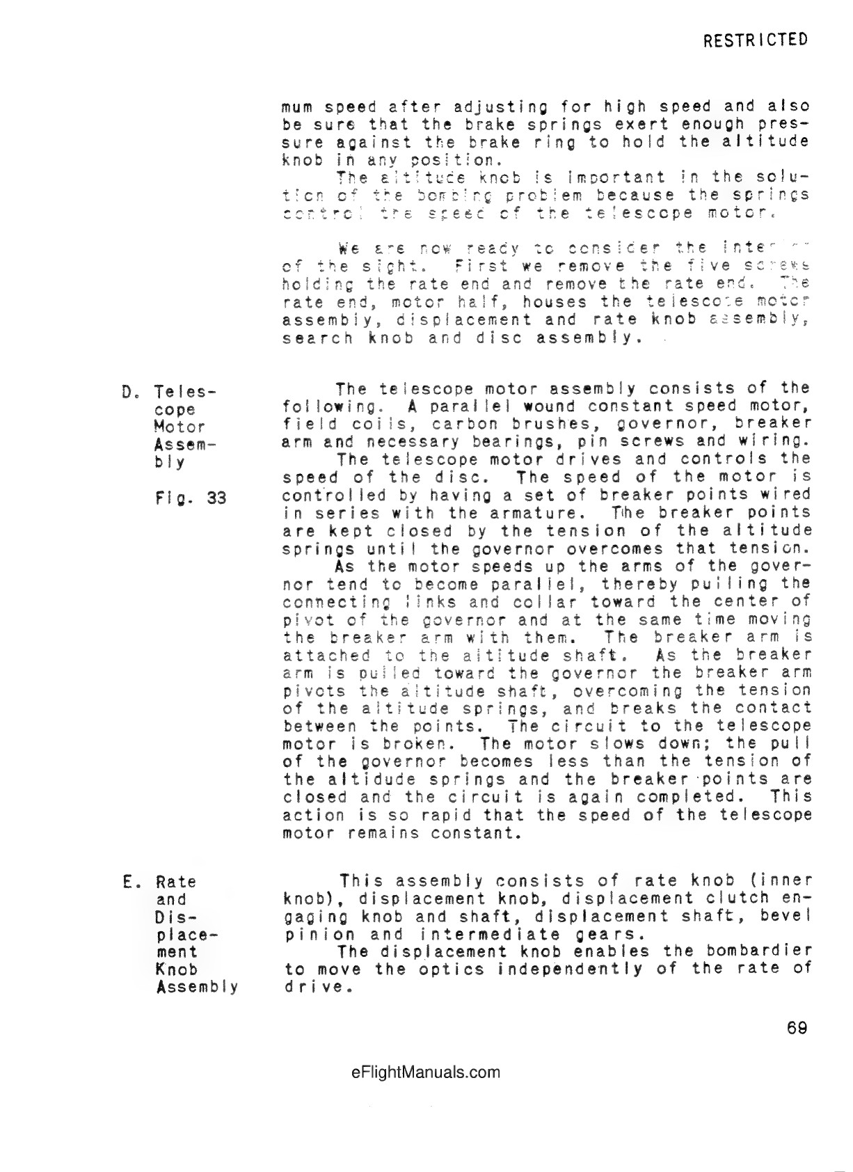
Motor governor and breaker mechanism context. No operational speed or targeting values inferred.
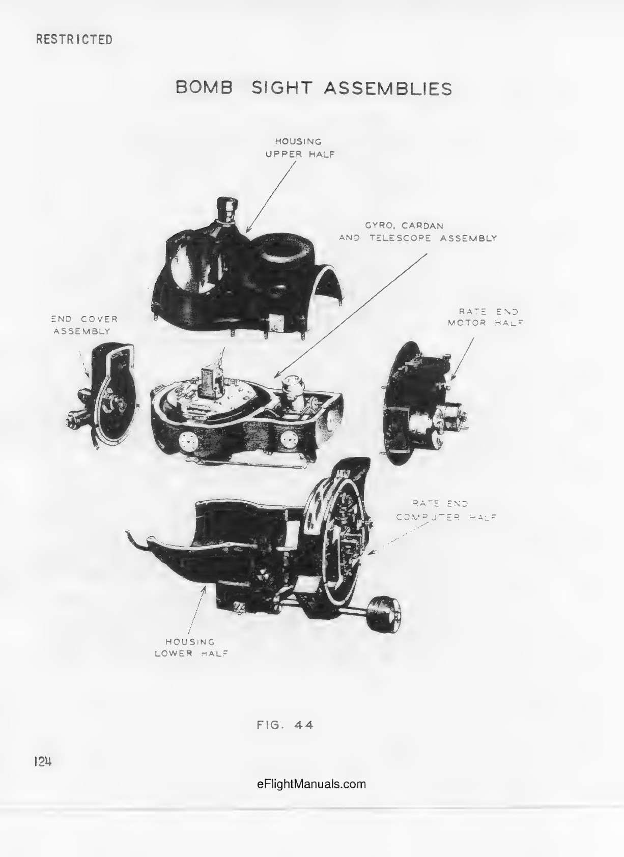
Five separated bench assemblies; printed page 124. Spacing is not installed clearance.
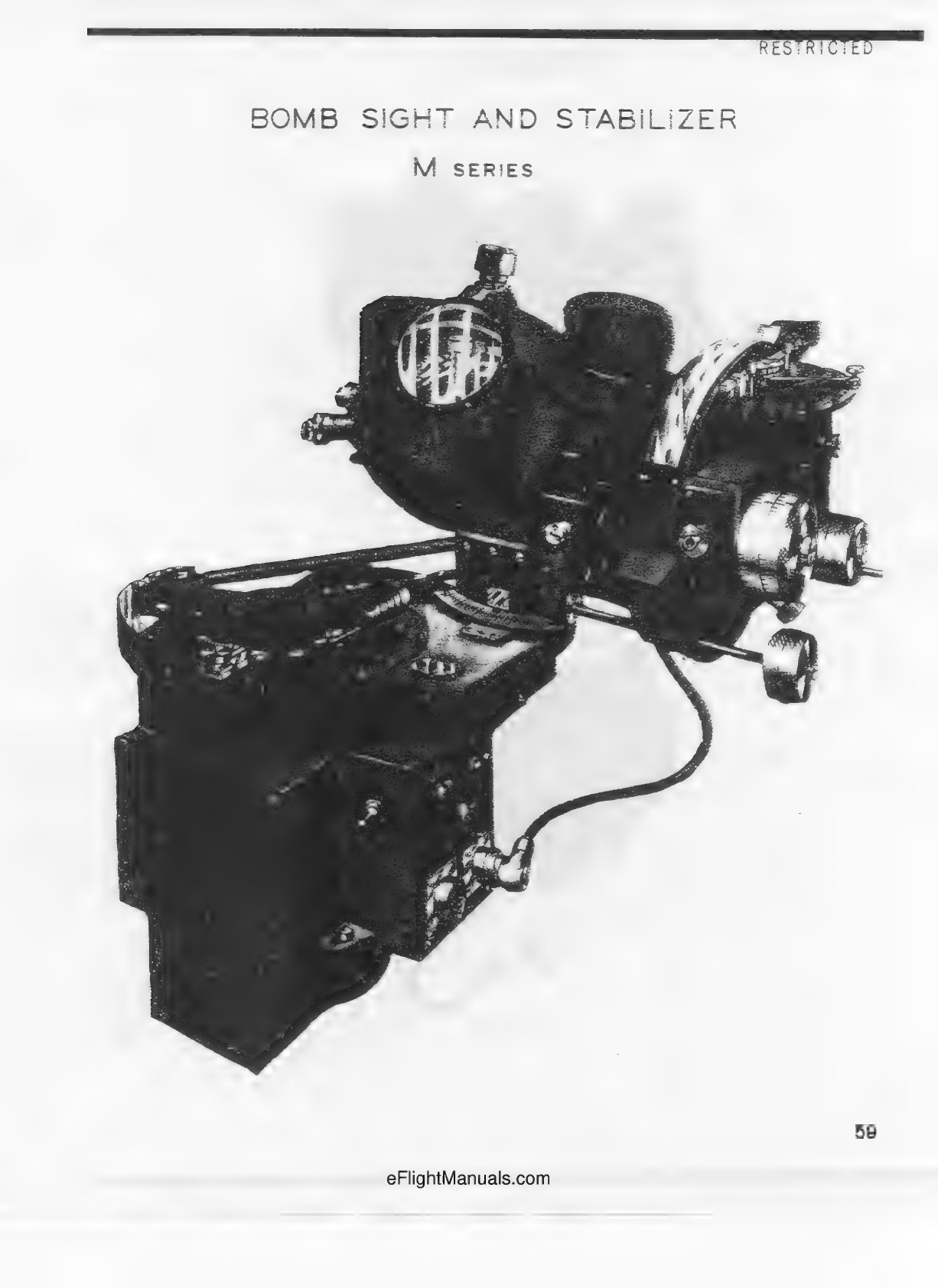
Bomb sight and stabilizer M series, assembled context.
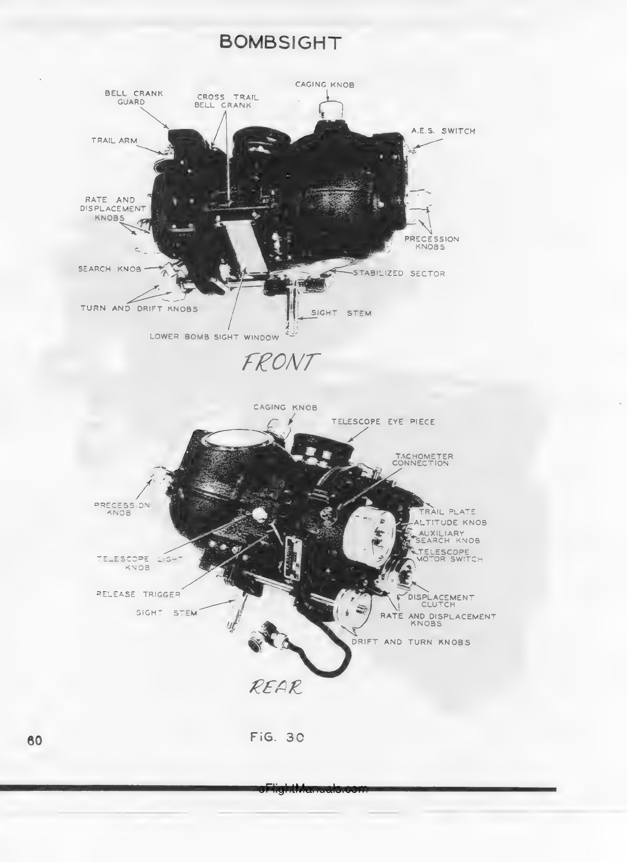
Front and rear assembled context, not an exploded silhouette target.
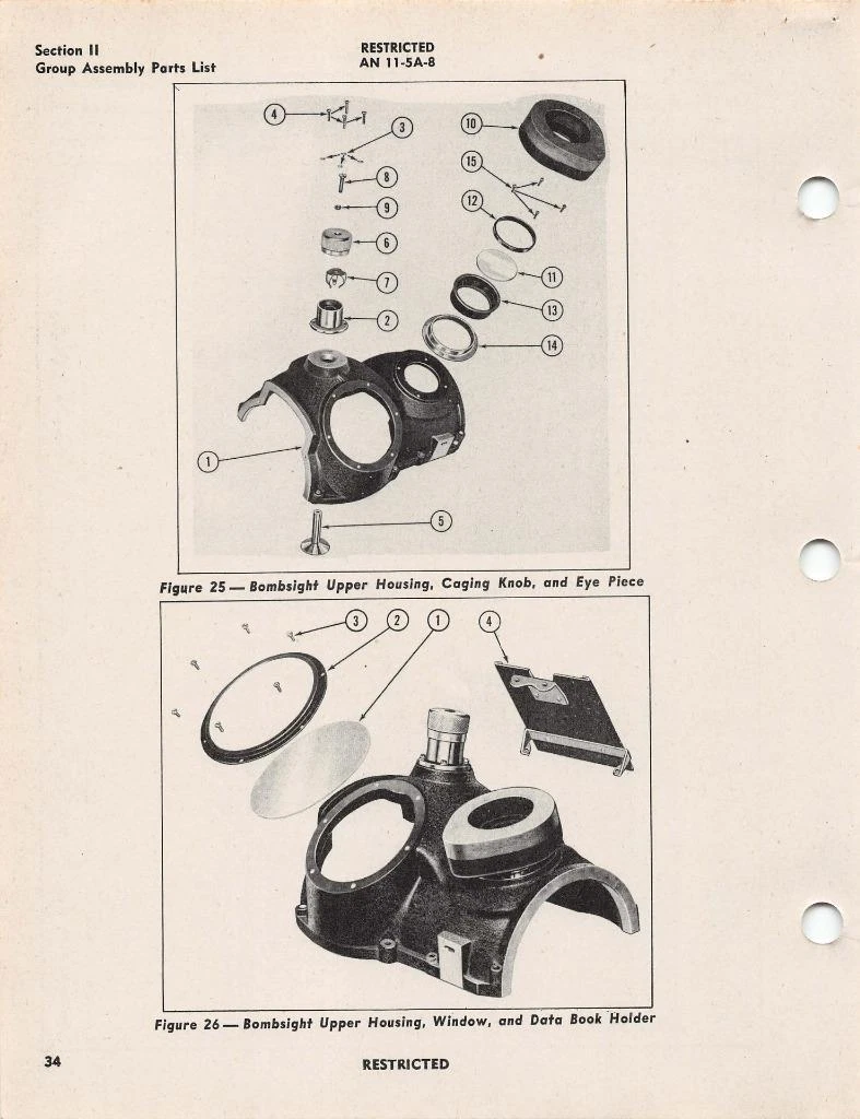
Complementary upper casting views, circular inspection window, ocular opening and data book holder.