Course knob assembly
The paired course controls and their shafts, gears and spring-loaded fittings at the sight end.
Follow the mechanism
Follow the two control shafts into their separate gear trains.
The drawing establishes their relative placement; exact tooth profiles and spring forces are not dimensioned.
Geometry follows the cited drawings and photographs. Unmeasured dimensions remain approximate; exploded spacing reveals existing model groups rather than a prescribed disassembly procedure.
Reference views
Inspect the full sheets as well as detail views. Figure numbers belong to their named document; similar-looking parts may be different variants.
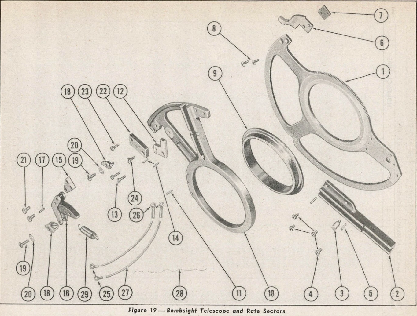
Telescope and rate sectors, NOT Fig.31 stabilized course sector. Inspected for identity; no geometric transfer or registered view.
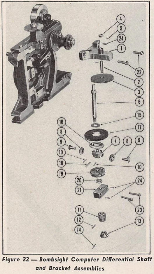
Differential shaft and bracket, distinct from course knobs; no dimensional transfer.
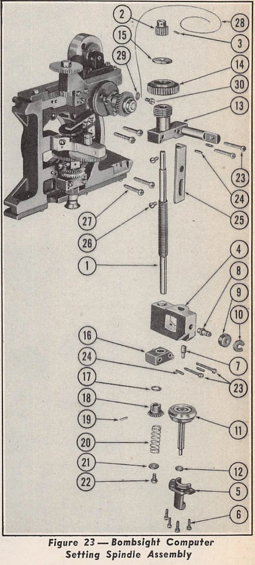
Computer setting spindle, distinct from course knobs. Not a hidden view of this mechanism.
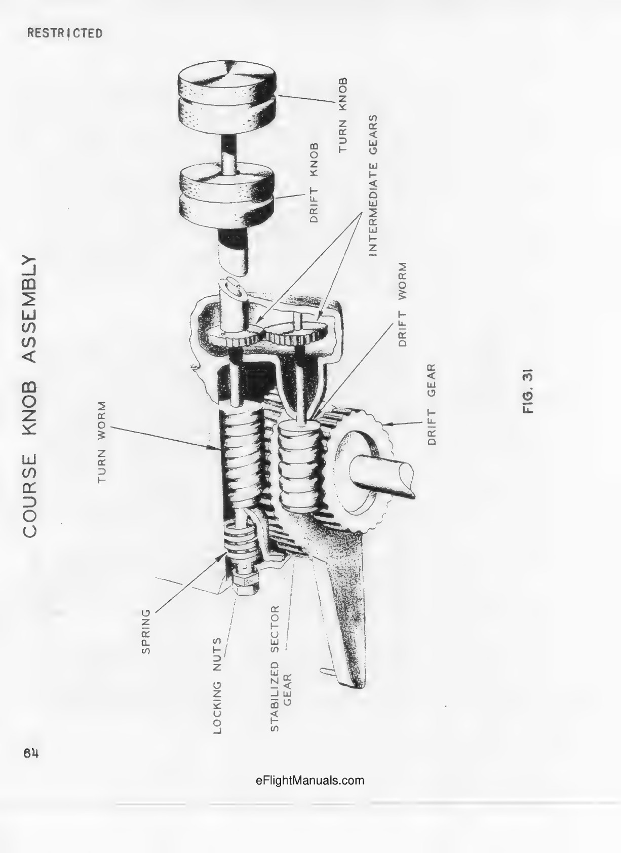
Printed p.64. Cutaway and broken control shaft; knob separation is illustrative, not installed clearance.
Printed p.63 establishes coaxial inner turn rod and outer drift shaft, intermediate pair and swivel-mounted drift worm.
Printed p.65 distinguishes stabilized sector and course operation from adjacent altitude assembly.